Trane Tracer TD7, User Manual
The Trane Tracer TD7, an advanced HVAC control system, ensures optimal energy efficiency and comfort. Equipped with cutting-edge features, this user-friendly device simplifies operations. Enhance your system's performance by downloading the free Trane Tracer TD7 User Manual from our website, manualshive.com, offering comprehensive instructions for convenient installation and usage.
Share
Download


Reviews:
No comments
Related manuals for Tracer TD7

7A3
Brand: Garland Pages: 154

HMV-A 0104
Brand: MAXA Pages: 35

MB6000
Brand: Nakayama Pages: 83

S-GT1830-LD
Brand: LANDY Pages: 7

5912311903
Brand: Scheppach Pages: 184

MPC 1200
Brand: Texas Pages: 28

Hobby 510B
Brand: Texas Pages: 40

Lilli 534B
Brand: Texas Pages: 64

KEM-140 DRS5 KH
Brand: Kaysun Pages: 60

CP138
Brand: Draper Pages: 30

Hyperchill ICE076
Brand: Parker Hiross Pages: 172

LSWD
Brand: Johnson Controls Pages: 38

RAPID RDA S Series
Brand: Vaderstad Pages: 122

GS8600
Brand: Nakayama Pages: 44

RD-ET03
Brand: Raider Pages: 78

Cool cabi OCA-S300AC-A100
Brand: OHM ELECTRIC Pages: 40

TE1318W1
Brand: LawnMaster Pages: 28
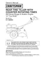
900 Series
Brand: Craftsman Pages: 52


