background image


SAFETY WARNING

Only qualified personnel should install and service the equipment. The installation, starting up, and servicing 
of heating, ventilating, and air-conditioning equipment can be hazardous and requires specific knowledge and 
training. Improperly installed, adjusted or altered equipment by an unqualified person could result in death or 
serious injury. When working on the equipment, observe all precautions in the literature and on the tags, 
stickers, and labels that are attached to the equipment.

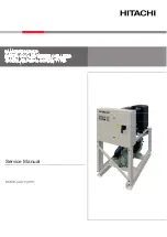
Cold Generator™ Scroll Liquid Chillers
Model CGWR and CCAR

20 to 65 Tons (60 Hz)
Water-Cooled and Compressor Chillers

Installation, Operation,
and Maintenance

CG-SVX038A-EN

September 2017

Summary of Contents for Cold Generator

Page 1: ...Improperly installed adjusted or altered equipment by an unqualified person could result in death or serious injury When working on the equipment observe all precautions in the literature and on the tags stickers and labels that are attached to the equipment Cold Generator Scroll Liquid Chillers Model CGWR and CCAR 20 to 65 Tons 60 Hz Water Cooled and Compressor Chillers Installation Operation and...

Page 2: ...ation which if not avoided could result in minor or moderate injury It could also be used to alert against unsafe practices NOTICE Indicates a situation that could result in equipment or property damage only accidents WARNING Proper Field Wiring and Grounding Required Failure to follow code could result in death or serious injury All field wiring MUST be performed by qualified personnel Improperly...

Page 3: ...Ingersoll Rand Environmental Health and Safety EHS policies when performing work such as hot work electrical fall protection lockout tagout refrigerant handling etc All policies can be found on the BOS site Where local regulations are more stringent than these policies those regulations supersede these policies Non Ingersoll Rand personnel should always follow local regulations WARNING Refrigerant...

Page 4: ...ction Check List and Unit Identification 9 Electrical Data 10 Dimensions and Weights 11 Installation 16 Unit Piping 19 Electrical Wiring 27 Unit Controller Software Installation and Setup 31 Unit Startup Procedures 33 Unit Shutdown 35 Unit Restart 36 Maintenance 37 Electrical Schematics 40 Appendix 63 ...

Page 5: ... Power Connection T Terminal Block D Non Fused Disconnect Switch F Fused Disconnect Switch Digit 16 Short Circuit Rating SCCR 0 Standard 5 kA Rating 1 Optional 100 kA Rating Digit 17 Sound Attenuator 0 No Sound Attenuation 3 Compressor Sound Blanket s 9 Factory Sound Enclosure Cabinet s Digit 18 Local Unit Controller Interface 0 Keypad with Dot Pixel Display 1 Color Touchscreen Digit 19 Remote BMS...

Page 6: ...nside door Optional 15 4 Color Touchscreen Keypad w Display comes standard Rigging Bracket Install Pockets Removable Water Plate on Shell and Tube Condenser Suction Line 1 per circuit TXV 1 per circuit Charging Port 1 per circuit Relief Valve 1 per circuit Filter Drier 1 per circuit Hot Gas Injection Solenoid Valve 1 per circuit Liquid Line 1 per circuit Solenoid Valve 1 per circuit Sight Glass 1 ...

Page 7: ... Circuit 2 2 Nominal compressor sizes based on 60 Hz a Compressor manufacturer sound power reported at rated compressor AHRI conditions measured in free space for individual compressors Table 2 General data for CCAR compressor chillers Unit Size 20 30 40 50 65 Compressor Quantity each 2 2 3 3 3 Nominal Tons tons 10 10 15 15 10 10 20 12 12 25 15 15 30 Steps of Unloading 100 50 100 50 100 75 50 25 1...

Page 8: ...essor chiller starting considerations and not by effectiveness of condenser ambient controls once the system is up and running Fan cycling and optimal low ambient dampers do not mitigate the low ambient starting challenge On a cold day with outdoor ambient temperature below 40 F the liquid line pressure at the expansion valve inlet in most circumstances is extremely low On start the suction pressu...

Page 9: ...d or inside the unit control box The Installation Operation and Maintenance manual can also be found in the unit control box Be sure to read all of this literature before installing and operating the unit Unit Description Trane CGWR water cooled chillers and CCAR compressor chillers condenserless chillers are designed for installation on a prepared surface in a suitable weatherproof location above...

Page 10: ...20 39 39 67 267 267 485 159 460 3 60 78 110 90 19 19 33 142 142 215 159 575 3 60 64 80 70 15 15 26 103 103 175 159 50 200 230 3 60 185 250 225 3 2 12 12 25 41 41 82 304 304 560 159 460 3 60 88 125 100 19 19 40 147 147 260 159 575 3 60 69 90 80 17 17 29 122 122 210 159 65 200 230 3 60 232 300 250 3 2 15 15 30 48 48 109 351 351 717 159 460 3 60 113 150 125 25 25 51 197 197 320 159 575 3 60 93 125 11...

Page 11: ... electrical data as required Refer to name plate on control box door inside for specific unit electrical data These documents can be forwarded for specific jobs as part of a job submittal package upon request Figure 1 CGWR CCAR 20 to 30 ton mechanical drawing B C A B 1 2 5 8 11 12 6 7 R N V W S U R N 3 4 D E F G T 4 PLACES M H I J K L 9 10 15 13 14 16 ...

Page 12: ...5 64 FPT N A N A Reference 1 Evaporator Water Inlet 9 Condenser Return Waterbox End CGWR only minimum clearance for maintenance 2 Evaporator Water Outlet 10 Condenser Inlet Outlet End CGWR only minimum clearance for maintenance 3 Condenser Water Inlet CGWR only 11 Condenser CGWR only 4 Condenser Water Outlet CGWR only 12 Evaporator 5 Power Disconnect Optional 13 Panel Power Section door swing 24 i...

Page 13: ...Dimensions and Weights CG SVX038A EN 13 Figure 2 CGWR CCAR 40 to 65 ton mechanical drawing C B B A 5 8 11 12 7 16 2 1 6 R N V W R N U S 3 4 G F D E T 4 PLACES M H I J K L 15 10 13 14 9 ...

Page 14: ...VIC 3 0 76 VIC 3 0 76 VIC 3 0 76 VIC 3 0 76 VIC 2 3 0 76 VIC 3 0 76 VIC 3 0 76 VIC 3 0 76 VIC 3 0 76 VIC 3 0 76 VIC 3 2 5 64 FPT 3 0 76 FPT 4 0 102 FPT N A N A N A 4 2 5 64 FPT 3 0 76 FPT 4 0 102 FPT N A N A N A Reference 1 Evaporator Water Inlet 9 Condenser Opposite Inlet Outlet End CGWR only minimum clearance for maintenance 2 Evaporator Water Outlet 10 Condenser Inlet Outlet End CGWR only minim...

Page 15: ...hts Shipping Operating Unit Size lbs kg lbs kg CGWR 20 1116 506 1042 473 30 1252 568 1242 563 40 1659 753 1577 715 50 1847 838 1833 831 65 2039 925 2005 909 CCAR 20 846 384 732 332 30 909 412 809 367 40 1265 574 1110 503 50 1304 591 1152 523 65 1484 673 1336 606 ...

Page 16: ...elief piping If necessary supply enough refrigerant and dry nitrogen 150 psig for pressure testing CCAR Start the unit under supervision of a qualified service technician Where specified supply and insulate the chilled water piping as required to prevent sweating under normal operating conditions Trane provides factory insulation on evaporator and related components Storage These units are designe...

Page 17: ...Other optional ship loose items may be attached to the skid or shipped separately depending on options selected Rigging Lifting Procedure If the CGWR CCAR is not moved using a forklift and the forklift pockets provided as part of the chiller s frame then the chiller should be lifted and moved by using the lifting rails as outlined in Step 1 through Step 8 A set of lifting rails is shipped loose an...

Page 18: ... be completed and promptly returned for review including the required running data log as instructed in the startup checklist Direct Mounting The unit can be installed directly on an isolated rigid mounting surface as long as the surface is level and will support the weight of the unit A mounting hole is provided at each of the unit mounting locations Provide a means of securely anchoring the unit...

Page 19: ...ement device must be installed in the water line Water Treatment Using untreated or improperly treated water in these units may result in inefficient operation and possible tube and or brazed plate damage Consult a qualified water treatment specialist to determine if treatment is needed Chilled Water Piping Chilled water piping and associated components shall be installed in accordance with Figure...

Page 20: ...ater regulating valve maintains condensing pressure and temperature by throttling water flow leaving the condenser in response to compressor discharge pressure Field supplied water regulating valves must be adjusted for proper operation during full load part load and transient conditions Field supplied water regulating valves must also be adjusted for proper positioning when unit is off Alternativ...

Page 21: ... Valve 2 Isolation Valves 3 Vibration Eliminators 4 Evaporator Heat Exchangers 5 Inlet and Outlet Chilled Water Lines 6 Valves for Pressure Measurement 7 a a Strainer with 20 mesh screen is required Strainer with 20 mesh screen 8 Evaporator Manual Air Vent Valve w Plug A Isolator Unit for initial water loop cleaning B b b Must account for water head difference when calculating total unit pres sure...

Page 22: ...on Eliminator Optional Water Regulating Valve UNIT FACTORY INSTALLED OPTIONS IF ORDERED T T P Condenser Out Condenser In Bypass Valve Isolation Valve Isolation Valve Pressure Gauge Temperature Gauge Temperature Gauge Valve for Pressure Measurement Valve for Pressure Measurement CUSTOMER PIPING ...

Page 23: ...25 30 35 0 00 2 00 4 00 6 00 8 00 10 00 12 00 14 00 16 00 18 00 20 00 0 5 2 0 0 2 0 5 1 0 0 1 0 5 0 Pressure Drop psi Flow GPM p p 20 TON 30 TON 40 TON 50 TON 65 TON Pressure Drop ft of H2O 0 00 5 00 10 00 15 00 20 00 25 00 0 00 2 00 4 00 6 00 8 00 10 00 12 00 14 00 16 00 18 00 0 0 50 0 100 0 150 0 200 0 250 0 Pressure Drop psi Flow GPM 30 TON 50 TON 40 TON 65 TON 20 TON ...

Page 24: ...15 16 18 22 2 21 3 19 6 82 24 80 63 77 65 56 59 55 32 52 98 28 2 27 3 25 6 15 16 18 22 9 22 1 20 7 83 51 82 06 79 57 57 59 56 45 54 49 28 9 28 1 26 7 20 22 24 17 9 15 9 13 7 74 75 71 42 67 86 50 69 48 08 45 30 23 9 21 9 19 7 20 22 24 19 2 17 5 15 6 76 96 74 07 70 92 52 43 50 16 47 69 25 2 23 5 21 6 25 26 28 12 7 11 4 9 2 66 28 64 27 60 95 44 07 42 50 39 91 18 7 17 4 15 2 25 26 28 14 6 13 7 11 5 69...

Page 25: ...e a 1 inch pitch toward the evaporator for every 10 feet of run 4 If the liquid line must be routed through an area warmer than outdoor air temperature insulate the line to prevent the refrigerant from flashing 5 A replaceable core liquid line filter drier must be installed as close as possible to the compressor chiller The core should be changed whenever the system is opened for service Trane com...

Page 26: ...field evacuation after leak checking use a vacuum pump capable of pulling a vacuum of 100 microns or less Follow the pump manufacturer s instructions for proper use of the pump Insure that all sections of the system are properly evacuated before proceeding Refrigerant Charging Once the system is properly installed leak tested and evacuated refrigerant charging can begin Liquid refrigerant must be ...

Page 27: ...possible interchange of wiring that makes a phase sequence indicator necessary if the operator is to quickly determine the phase rotation of the motor Setting Proper Electrical Phase Sequence Propercompressormotorelectricalphasingcanbequickly determined and if necessary corrected before starting the unit Use a quality instrument such as an Associated WARNING Proper Field Wiring and Grounding Requi...

Page 28: ...n of the three voltages three phases subtracted from the average without regard to sign divided by the average voltage Example If the three voltages measured at the line voltage fused disconnect are 221 volts 230 volts and 227 volts the average would be 221 230 227 226 volts 3 The percentage of imbalance is then 100 226 221 2 2 226 In the preceding example 221 is used because it is the farthest fr...

Page 29: ... to 10 Vdc analog output to control a head pressure control valve Consult wiring diagram located inside the control box door for connection point s Equipment Grounds Provide proper grounding at the connection point provided in the unit control panel Unit Controller Note The unit controller section inthis IOMcontains only a brief overview of the unit controller Please consult the Unit Controller Ve...

Page 30: ...l information needed to run the unit is available from the unit display however a laptop computer is invaluable for ease of use of diagnosing or changing the unit setpoints Note Not all setpoints can be changed with MCS Connect some require a configuration change A serial cable is included in each shipment for the convenience of the field tech If you do not have a laptop with a serial port you wil...

Page 31: ... 1008 packets of data replacing the oldest with the newest With the time interval set at 10 seconds you can download graph data with a time span of 168 minutes The time interval is adjustable In the MCS CONNECT software select GRAPH Data will be downloaded and then a graph setup page will appear Select the input and output data you want to look at Type in Y axis parameters and select OK Use the sc...

Page 32: ...D screen After the file is uploaded the Trane MCS Digital Controller will verify that it s a valid file and then erase the flash memory Next it will write the new hex to memory When completed the controller will reboot itself This process may take 15 or 20 minutes After the reboot is completed close and restart the MCS CONNECT software to reestablish communication with the chiller ...

Page 33: ...mage To prevent overheating at connections and under voltage conditions at the compressor motor check tightness of all connections in the compressor power circuit To prevent compressor damage do not operate the unit with discharge or liquid line service valves closed The use of untreated or improperly treated water in a Chiller may result in scaling erosion corrosion algae or slime It is recommend...

Page 34: ...nt shortage charge refrigerant into each circuit Refrigerant shortage is indicated if operating pressures are low and sub cooling is also low If suction and discharge pressures are low but sub cooling is normal no refrigerant shortage exists Adding refrigerant will result in overcharging Add refrigerant with the unit running by metering liquid refrigerant through the Schrader valve between the exp...

Page 35: ...lectrical disconnect and unit mounted disconnect if used and lock in open position Chiller Level Local Stop Normal Latching Diagnostic Chiller Level Non Latching Diagnostic Tracer Stop External Auto Stop Stopped Shutting Down De Energize Condenser Water Pump Relay If Chiller Controls Pump Stopped or Run Inhibit Running Run Inhibit Evap Pump Off Delay Timer 0 to 30 Minutes Circuit 1 Shutting Down A...

Page 36: ... piping connections for leakage Make any necessary repairs 6 With water pump s running adjust chilled water flow and check water pressure drop through the evaporator 7 Check the flow switch on the evaporator outlet piping for proper operation 8 Stop the water pump s 9 Complete each step in Trane literature CGWR ADF002 EN Start upCheckListforCGWRand CCAR Chillers 10 Energize Crankcase Heaters Must ...

Page 37: ...lity test i e a test where the liquid line valve is closed and the compressor is pumped in a vacuum to see if it will pump down and hold If fact this kind of test may actually damage the scroll compressor The proper procedure for checking scroll compressor operation is outlined below 1 Verify that the compressor is receivingsupply powerof the proper voltage 2 With the compressor running measure th...

Page 38: ... thermostat Note Operation of the chiller with saturated suction temperatures below freezing will cause damage to the evaporator If this occurs immediately stop the machine diagnose and correct the problem Periodic Maintenance Performall of the indicated maintenance procedures at the intervals scheduled This will prolong the life of the unit and reduce the possibility of costly equipment failure W...

Page 39: ...for unusual conditions Review the weekly operating log for conditions history for the unit and take note of any unusual trends in performance Take appropriate preventative actions if necessary Annually Perform all weekly and monthly maintenance procedures Have a qualified service technician check the setting and function of each control and inspect the condition of and replace compressor and contr...

Page 40: ...e Run Stop Control Panel Representation 4 Optional For CGWR 40 65 ton Cooling Tower Pump Enable Hazardous voltage Optional WARNING Disconnect all electrical power Optional Alarm Dry Contacts Optional Flow Switch flow proving device 4 5 Interface requirements including remote disconnects before Required Factory supplied or approved alternate field installed flow 5 proving device connection Use copp...

Page 41: ...NOID LP1SW TBA10 TBA11 TBA20 RED 3 UNIT CONTROLLER 3G SENSOR M 16 REM RUN STOP CMP1 2 ENABLE SENSOR M 13 GND 12V GND ETHERNET WRV Com NO NC Shield tied at this end ETHERNET 12V MCS IORS485 SENSOR 12 SENSOR 11 SENSOR 10 SENSOR 9 SENSOR 8 SENSOR 7 SENSOR 5 SENSOR 6 SENSOR 3 SENSOR 4 SENSOR 1 SENSOR 2 DI 15 DI 16 DI 13 DI 14 5 5 5 DIGITAL INPUTS ANALOG OUTS A 3 A 4 A 1 A 2 gnd gnd 485 485 SCL SDA GND...

Page 42: ...LD BLACK BLACK SHIELD OPTIONAL TOUCHSCREEN CONNECTOR TO UNIT Optional Touchscreen 3 3A OPTIONAL FIELD SPARE WHITE TO TBC3 SHIELD TO TBC1 BLACK SHIELD WHITE RED BLACK SHIELD BLACK SHIELD WHITE TO AO1 TBC 3 U Y1 Bellimo WRV 1 WHITE RED 3B 120 VAC TR3 OPTIONAL 24 VAC TBC 2 TBC 1 120 VAC FU1 FU2 FU3 2 1 RED WHITE TR1 T3 T2 T1 L3 C1 L2 L1 C3 C1 AUX 1 CCH 1 T3 T1 WHITE To Customer Interface or Communica...

Page 43: ...TION FU1 FU2 FU3 AMPS 2 PRIMARY KLDR3 LITTELFUSE FOR 208 230V UNITS 1 2 1 CPS On Off POWER DISTRIBUTION BLOCK PDB1 208 240 480 120 VAC 250 VA TRANSFORMER TR1 COMPRESSOR CONTACTORS TR1 SECONDARY CIRCUIT FUSE KLDR OR EQ TR1 PRIMARY CIRCUIT FUSES KLDR OR EQ DISCONNECT SWITCH FU1 FU2 FU3 DSW1 C1 C2 LEGEND UNIT CONTROLLER UC COMMUNICATIONS MODULE COM CURRENT TRANSFORMER MODULES CT1 CT2 ITEMS MARKED WIT...

Page 44: ...NSFORMER FUSE SCHEDULE FUSE TYPE LITTELFUSE TRANSFORMER LOCATION FOR 460V UNITS 1 CPS On Off POWER DISTRIBUTION BLOCK PDB1 208 240 480 120 VAC 250 VA TRANSFORMER TR1 COMPRESSOR CONTACTORS TR1 SECONDARY CIRCUIT FUSE KLDR OR EQ TR1 PRIMARY CIRCUIT FUSES KLDR OR EQ DISCONNECT SWITCH FU1 FU2 FU3 DSW1 C1 C2 LEGEND UNIT CONTROLLER UC COMMUNICATIONS MODULE COM CURRENT TRANSFORMER MODULES CT1 CT2 120 24 V...

Page 45: ... TYPE LITTELFUSE TRANSFORMER LOCATION 1 CLASS CC 1 1 4 600 VOLTS 100 5564A FOR 575V UNITS GND TERMINAL BLOCK TBA POWER DISTRIBUTION BLOCK PDB1 600 VAC 250 VA TRANSFORMER TR1 COMPRESSOR CONTACTORS TR1 SECONDARY CIRCUIT FUSE KLDR OR EQ TR1 PRIMARY CIRCUIT FUSES KLDR OR EQ DISCONNECT SWITCH FU1 FU2 FU3 DSW1 C1 C2 LEGEND UNIT CONTROLLER UC COMMUNICATIONS MODULE COM CURRENT TRANSFORMER MODULES CT1 CT2 ...

Page 46: ...PS VOLTS FU1 FU2 PRIMARY TRANSFORMER CC 3 1 2 600 FU3 SECONDARY TRANSFORMER LITTELFUSE KLDR3 2 1 CC 3 1 2 600 FU4 FU5 FU6 DIGITAL POWER MONITOR 0 0 6 1 1 K T K N O R T I M I L LITTELFUSE KLDR3 2 NOTES 1 ITEMS MARKED WITH ARE OPTIONAL AND ARE NOT ON ALL UNITS 23 FU4 6 230V TR1 FU3 SCHEDULE FUSE SW 2 1 PWM C2 FU1 2 C3 C1 GND DSW1 CT3 CT2 CT1 PDB1 TBA TR3 23 EXP1 UC 3 CKT2 Enable RELAY M 1 RELAY M 2 ...

Page 47: ...U2 PRIMARY TRANSFORMER LITTELFUSE KLDR1 2 1 CC 1 1 2 600 FU3 SECONDARY TRANSFORMER LITTELFUSE KLDR3 2 1 CC 3 1 2 600 FU4 FU5 FU6 DIGITAL POWER MONITOR 0 0 6 1 K T K N O R T I M I L NOTES 1 ITEMS MARKED WITH ARE OPTIONAL AND ARE NOT ON ALL UNITS FU4 6 230V TR1 FU3 SCHEDULE FUSE SW 2 1 PWM C2 FU1 2 C3 C1 GND DSW1 CT3 CT2 CT1 PDB1 TBA TR3 23 EXP1 UC 3 CKT2 Enable RELAY M 1 RELAY M 2 RELAY M 3 UNIT CO...

Page 48: ...T C U D O R P 5 2 0 0 0 5 0 8 R 1 1 9 27 13 1 1 SMH SMH BAR NOTES 1 ITEMS MARKED WITH ARE OPTIONAL AND ARE NOT ON ALL UNITS TBA FU4 6 230V TR1 FU3 SCHEDULE FUSE SW 2 1 PWM C2 FU1 2 C3 C1 GND DSW1 CT3 CT2 CT1 PDB1 TR3 23 EXP1 UC 3 CKT2 Enable RELAY M 1 RELAY M 2 RELAY M 3 UNIT CONTROLLER RELAY M 5 RELAY M 4 RELAY M 6 RELAY M 8 RELAY M 7 RELAY M 9 Voltage 115v RELAY M 10 3 TBC 3 4 2 1 3 4 2 1 COM 9 ...

Page 49: ... conductors only CAUTION Failure to do so can cause death or equipment damage to use copper conductors may cause accept other type conductors Failure Unit terminals are not designed to serious injury cannot be inadvertently energized tagout procedures to ensure power servicing unit Follow proper lockout Notes All three phase motors supplied with the unit are protected under 1 primary single phase ...

Page 50: ...tart up procedures have been completed damper per AO Wiring to be 2 wire shielded cable between outdoor If installing with a Trane CAUJ air cooled condenser more specific 7 field wiring instructions can be found in the operations and maintenance manual Use copper conductors only CAUTION Failure to do so can cause death or equipment damage to use copper conductors may cause accept other type conduc...

Page 51: ...ANALOG 5 GND SI SENSOR M 1 CW IN DIGITAL ANALOG Termination HGS 1 HOT GAS SOLENOID LP1SW TBA10 TBA11 TBA20 RED 3 UNIT CONTROLLER FLOW Field SENSOR M 16 REM RUN STOP CMP1 2 ENABLE V L OPTIONAL TOUCHSCREEN DAMPER CONTROL TO KEYPAD DISPLAY Com NO NC Shield tied at this end ETHERNET 12V MCS IORS485 SENSOR 12 SENSOR 11 SENSOR 10 SENSOR 9 SENSOR 8 SENSOR 7 SENSOR 5 SENSOR 6 SENSOR 3 SENSOR 4 SENSOR 1 SE...

Page 52: ...ONAL FIELD SHIELD BLACK SHIELD WHITE RED BLACK SHIELD BLACK SHIELD WHITE 120 VAC FU1 FU2 FU3 2 1 RED WHITE TR1 T3 T2 T1 L3 C1 L2 L1 C3 C1 AUX 1 CCH 1 T3 T1 OPTIONAL TOUCHSCREEN POWER SOURCE L T2 CCH 3 3 COMPR CKT 1 L3 L2 L1 PDB1 DSW1 DISCONNECT OPTIONAL OPTIONAL GROUND PANEL Menu 8 7 5 1 4 6 2 3 12v Gnd SCL SDA 485 485 T3 T2 COMPR C3 AUX 3 1 COMPR CKT 2 C2 AUX 2 CCH 2 L3 L2 L1 L3 L2 L1 COMPRESSOR ...

Page 53: ... EN 53 Figure 21 Power schematic CAUJ condenser control circuit modification fan cycling control by CCAR compressor chillers 1TB2 1 34 1TB3 5 64 1TB3 4 63 1TB3 6 65 C A E C D A B C D B G G 1TB3 9 A 76 E E E 1TB3 10 77 F F C 1TB3 11 78 ...

Page 54: ...ff The installed pressure switch will not be used A Instructions Reference The installed pressure switch will not be used Remove wire 64E Connect 1TB3 5 to TBD 2 at Trane Chiller This is the first fan on and last fan off COMPLETE Circle Remove wire 76A Connect 1TB3 9 to TBD 7 at Trane Chiller This is the last fan on and first fan off first fan off The installed pressure switch will not be used Ste...

Page 55: ...iagrams CAUJ condenser control circuit modification low ambient damper control by CCAR compressor chillers 839 851 9 3 J2 3 P2 3 848A 2TB34 9 851 2TB34 10 A 10 839 C A B F B 2U83 J2 4 P2 4 849A 851A 839F B P2 C J2 C 2U83 A A F A 2TB34 Low Ambient Schematic Wiring Diagram Low Ambient Connections Diagram ...

Page 56: ...sconnect plug 2U83P2 from the damper control box Ambient Damper Control by Trane CCAR Compressor Chiller Reference Circle Instructions 1 A B Reference Trane CAUJ Condenser Control Trane CAUJ Condenser Control Circuit Modification COMPLETE NOTES All CCAR CAUJ applications require that the CCAR Compressor Chiller control the condenser ambient dampers when applicable For Ambient Control Dampers when ...

Page 57: ... FU3 AMPS 2 PRIMARY KLDR3 LITTELFUSE KLDR3 TRANSFORMER SECONDARY 2 1 CC 3 1 2 TRANSFORMER FUSE SCHEDULE FUSE TYPE FOR 208 230V UNITS GND GROUND LUG TBA POWER DISTRIBUTION BLOCK PDB1 208 240 480 120 VAC 250 VA TRANSFORMER TR1 COMPRESSOR CONTACTORS TR1 SECONDARY CIRCUIT FUSE KLDR OR EQ TR1 PRIMARY CIRCUIT FUSES KLDR OR EQ DISCONNECT SWITCH FU1 FU2 FU3 DSW1 C1 C2 LEGEND UNIT CONTROLLER UC COMMUNICATI...

Page 58: ...1 2 600 VOLTS 100 5564 600 DESIGNATION FU1 FU2 FU3 AMPS 2 PRIMARY KLDR1 LITTELFUSE KLDR3 TRANSFORMER SECONDARY 2 1 CC FOR 460V UNITS GROIUND LUG GND TBA POWER DISTRIBUTION BLOCK PDB1 208 240 480 120 VAC 250 VA TRANSFORMER TR1 COMPRESSOR CONTACTORS TR1 SECONDARY CIRCUIT FUSE KLDR OR EQ TR1 PRIMARY CIRCUIT FUSES KLDR OR EQ DISCONNECT SWITCH FU1 FU2 FU3 DSW1 C1 C2 LEGEND UNIT CONTROLLER UC COMMUNICAT...

Page 59: ...ONDARY 2 1 CC 3 1 2 TRANSFORMER FUSE SCHEDULE FUSE TYPE LITTELFUSE TRANSFORMER LOCATION 1 CLASS CC 1 1 4 600 VOLTS 100 5564A FOR 575V UNITS 17 GND TOOGLE SWITCH POWER DISTRIBUTION BLOCK PDB1 600 VAC 250 VA TRANSFORMER TR1 COMPRESSOR CONTACTORS TR1 SECONDARY CIRCUIT FUSE KLDR OR EQ TR1 PRIMARY CIRCUIT FUSES KLDR OR EQ DISCONNECT SWITCH FU1 FU2 FU3 DSW1 C1 C2 LEGEND UNIT CONTROLLER UC COMMUNICATIONS...

Page 60: ... CLASS AMPS VOLTS FU1 FU2 PRIMARY TRANSFORMER CC 3 1 2 600 FU3 SECONDARY TRANSFORMER LITTELFUSE KLDR3 2 1 CC 3 1 2 600 FU4 FU5 FU6 DIGITAL POWER MONITOR 0 0 6 1 1 K T K N O R T I M I L LITTELFUSE KLDR3 2 NOTES 1 ITEMS MARKED WITH ARE OPTIONAL AND ARE NOT ON ALL UNITS 7 8 TBD TR1 FU3 SCHEDULE FUSE SW 2 1 PWM C2 FU1 2 C3 C1 GND DSW1 CT3 CT2 CT1 PDB1 TBA 6 2 EXP1 UC 3 CKT2 Enable RELAY M 1 RELAY M 2 ...

Page 61: ... FU1 FU2 PRIMARY TRANSFORMER LITTELFUSE KLDR1 2 1 CC 1 1 2 600 FU3 SECONDARY TRANSFORMER LITTELFUSE KLDR3 2 1 CC 3 1 2 600 FU4 FU5 FU6 DIGITAL POWER MONITOR 0 0 6 1 K T K N O R T I M I L NOTES 1 ITEMS MARKED WITH ARE OPTIONAL AND ARE NOT ON ALL UNITS CT1 1 9 TR1 FU3 SCHEDULE FUSE SW 2 1 PWM C2 FU1 2 C1 C3 GND DSW1 CT3 CT2 2 PDB1 TBA 6 3 EXP1 UC 3 CKT2 Enable RELAY M 1 RELAY M 2 RELAY M 3 UNIT CONT...

Page 62: ...V CONTROL PANEL LAYOUT CCAR SCROLL 410A COMPRESSOR CHILLER NOTES 1 ITEMS MARKED WITH ARE OPTIONAL AND ARE NOT ON ALL UNITS TR1 18 9 4 PDB1 FU3 SCHEDULE FUSE SW 2 1 PWM C2 FU1 2 C3 C1 GND DSW1 CT3 CT2 CT1 6 2 3 TBA EXP1 UC 3 CKT2 Enable RELAY M 1 RELAY M 2 RELAY M 3 UNIT CONTROLLER RELAY M 5 RELAY M 4 RELAY M 6 RELAY M 8 RELAY M 7 RELAY M 9 Voltage 115v RELAY M 10 3 COM 9 9 2 1 4 3 2 1 4 3 7 5 6 8 ...

Page 63: ...on screw machines 2 For high amp motor overload protection 4 Used in kw calculations The MCS CT300 is a solid core version so the conductor runs through the sensor No cutting taping or rerouting is required It is accurate reliable easy to install and requires no service The MCS CT300 has an accuracy of 3 amps in the frequency range from 50 60Hz The sensor outputs a 0 to 5vdc signal The sensor powe...

Page 64: ...ight environment an strain relief 100 10 200 1 70 300 2 30 400 2 90 500 3 50 600 4 10 56 110 16 210 1 76 310 2 36 410 2 96 510 3 56 610 4 16 62 120 22 220 1 82 320 2 42 420 3 02 520 3 62 620 4 22 68 130 28 230 1 88 330 2 48 430 3 08 530 3 68 630 4 28 74 140 1 34 240 1 94 340 2 54 440 3 14 540 3 74 640 4 34 80 150 1 40 250 2 00 350 2 60 450 3 20 550 3 80 650 4 40 86 160 1 46 260 2 06 360 2 66 460 3...

Page 65: ... 175 38 3 3 293 758 1 270 104 40 51 050 3 310 165 73 8 13 456 4 407 212 100 5 573 4 736 25 31 6 2 299 670 0 208 40 4 4 277 040 1 326 105 40 5 49 846 3 337 167 75 12 930 4 428 215 101 6 5 289 4 749 20 28 9 1 921 640 0 247 45 7 2 239 686 1 472 110 43 3 44 287 3 465 170 76 6 12 185 4 457 218 103 3 5 020 4 761 15 26 1 1 610 592 0 292 50 10 207 850 1 624 113 45 41 290 3 539 175 79 4 11 052 4 502 220 10...

Page 66: ... corrosive atmosphere abuse or improper use or misapplication such as breakage by negligence accident vandalism the elements shock vibration or exposure to any other service range or environment of greater severity than that for which the products were designed or if operation is contrary to NAPPS or manufacturer s recommendation or if the serial number has been altered defaced or removed Hermetic...

Page 67: ......

Page 68: ...ldings transport and protect food and perishables and increase industrial productivity and efficiency We are a global business committed to a world of sustainable progress and enduring results ingersollrand com Ingersoll Rand has a policy of continuous product and product data improvement and reserves the right to change design and specifications without notice We are committed to using environmen...

Reviews: