


Installation
CAUC-IOM-8
Operation
Maintenance
e
r
u
t
a
r
e
ti
L
e
c
i
v
r
e
S
y
r
a
r
b
i
L
n
o
it
a
r
e
g
ir
f
e
R
n
o
it
c
e
S
t
c
u
d
o
r
P
Product
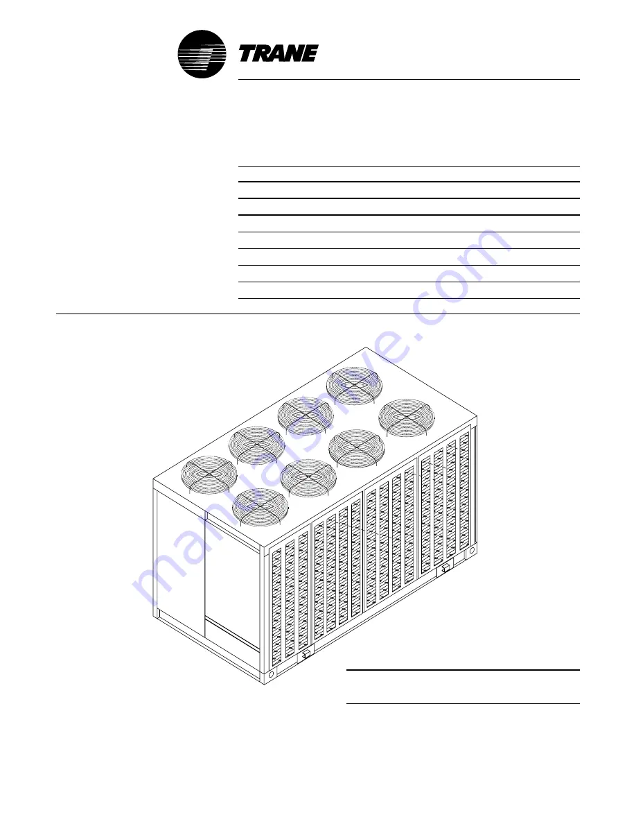
Air Cooled Condenser
Model
CAUC
e
c
n
a
n
e
t
n
i
a
M
/
n
o
it
a
r
e
p
O
/
n
o
it
a
ll
a
t
s
n
I
e
p
y
T
e
r
u
t
a
r
e
ti
L
8
e
c
n
e
u
q
e
S
Date
October 2008
File No.
SV-UN-S/S-CAUC-IOM-8 10/08
December 2001
s
e
d
e
s
r
e
p
u
S
TM
Remote Air Cooled Condensers
© 2008 Trane All rights reserved
http://www.trane.com
Models
"J" and Later Design Sequence
CAUC-C80
CAUC-D10
CAUC-D12
Note: The installation of this equipment must
comply with all National, State, and Local
Codes.
Since the manufacturer has a policy of continuous product
improvement, it reserves the right to change specifications and
design without notice.
Summary of Contents for CAUC-C80
Page 8: ...8 Figure 3 2 CAUC C80 Unit Dimensional Data Recommended Clearances ...
Page 9: ...9 Figure 3 2 Continued CAUC D10 Unit Dimensional Data Recommended Clearances ...
Page 10: ...10 Figure 3 2 Continued CAUC D12 Unit Dimensional Data Recommended Clearances ...
Page 19: ...19 Installation Continued Figure 3 5 Typical CAUC C80 through D12 Field Wiring Diagram ...
Page 28: ...28 Figure 5 2 Typical Wiring Schematic for 80 through 120 Ton Units ...
Page 29: ...29 ...
Page 30: ...30 Figure 5 3 Typical Control Panel Connections Diagram for 80 through 120 Ton Units ...
Page 31: ...31 ...
Page 36: ...36 ...


