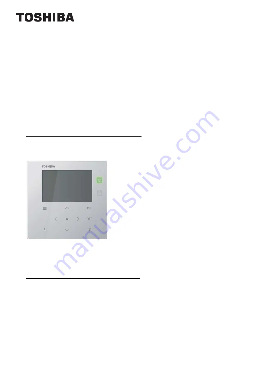
Summary of Contents for TCB-SC643TLE

Page 1: ...ual Air Conditioning Control System Central remote controller Contents 1 Safety Precautions 2 2 Included Items 3 3 Outline drawing 3 4 How to perform wiring 4 5 How to install 7 6 Centralized controller test run 8 7 Various setting methods 10 ...

Page 2: ... do not require hospitalization or long term outpatient treatment 3 Damage to property refers to extended damage related to houses household goods livestock or pets etc WARNING Prohibited Do not modify the unit Doing so may result in excessive heat or fire Instructions Installation and reinstallation should be performed by your vendor or a qualified electrician Attempting to carry out installation...

Page 3: ... drawing Component name Form Q ty Remark Central remote controller 1 Main unit Manual 1 Operation Manual 1 Installation Manual CD R 1 Included only for TCB SC643TLE Fastening screw 4 M4 20 4 M3 8 16 wood screw 50 6 68 4 20 70 6 120 120 100 83 5 68 4 84 46 88 Φ3 5 Φ4 5 6 5 77 100 ...

Page 4: ...e power supply wiring Be sure to install a breaker or an all pole isolating switch on the primary side of the equipment side power supply of TCC LINK and digital input output No Wiring Wire type wire diameter wire length 1 For TCC LINK Microphone cord shielded two core for instrumentation 1 25 mm2 up to 1000 m 2 00 mm2 up to 2000 m total extension distance 2 For power supply H07 RN F or 245IEC66 0...

Page 5: ...he terminal block When connecting with an optional weekly timer connect it to the WT connector Connect the power supply wire to the ground wire Connect the signal wires Cover fixing screw Screws indicated by arrows Cover fixing screw Power supply cover Rear side terminal block Power terminal Power supply wire Clamp Ground wire Ground terminal Rubber bushing Remove the transparent cover at installa...

Page 6: ...Fasten the screws to the terminal with torque of 0 5 N m COM DI3 DI2 DI1 COM DO2 DO1 U1 U2 Input common Not used All start input All stop input Control input Output common Operation output Alarm output State output Name I O Item This unit side Equipment side I O conditions Circuit Terminal name Circuit example I O conditions Digital I O terminal State output Alarm output Operation output No voltag...

Page 7: ...ity or water Dusty locations Locations in direct sunlight and locations subject to high temperatures Locations within 1 m from televisions or radios Outdoors under awnings or other locations exposed to rain and dew CAUTION Do not wire communication lines outdoor indoor transition wiring central control line wiring or input output wiring next to power supply wiring etc or house them in the same met...

Page 8: ...er completing the air conditioner test run When configuring various settings with the centralized controller it is necessary to first complete initial communication with all connected indoor outdoor units Perform the setting work at least 10 minutes after turning on the power NOTE If you configure the central control address setting before initial communication is fully completed units with no set...

Page 9: ... of Servicing Menu Return to the All screen and check whether the displayed number of units matches the number of units that were registered to the zones 2 2 Indoor units that have not been registered to a zone are not included in the number of units on the All screen 5 Operation confirmation Confirm that the indoor units operate from the centralized controller Also check whether the operation of ...

Page 10: ...reen 4 Press to select a Zone to change then press Confirm The Select character screen appears Setting items Description Reference page 1 Zone Name Settings Register the names of zones 1 to 10 10 Screen Display Settings 2 Language Set language of screen display 11 3 Screen Contrast Adjust the contrast density of the LCD 11 4 Backlight Set the LCD backlight to ON OFF for 15 seconds or 30 seconds 11...

Page 11: ...The Screen Contrast screen appears 3 Move with and adjust the contrast then press Confirm The adjusted contrast is set Press Return to return to the Screen Display Settings selection screen 4 Backlight 1 Display the Screen Display Settings screen 2 Press and to select 3 Backlight then press Confirm The Backlight screen appears indicates the currently set item 3 Press and to select the lighting tim...

Page 12: ...ct 2 Long press time then press Confirm The ON long press time screen appears 7 Press and to select the number of seconds 1 to 5 seconds then press Confirm The long push time of the ON button is set to the selected number of seconds Press Return to return to the ON butt long press screen 7 Sensitivity Adjustment 1 Display the Button Settings screen 2 Press and to select 3 Sensitivity Adjustment th...

Page 13: ...a mistake in the password the message Wrong Password Enter the correct password appears 2 Enter the password with then press Confirm The Admin Password Change screen appears Press and to change the number You can change the digit with and 3 Press to enter a new password then press Confirm The new password is set and the display returns to the Settings Menu screen NOTE The initial set password for ...

Page 14: ... 15 Address Settings 3 Obtain Address Obtain centralized address information manually 16 4 Address Display Display centralized address information 16 5 Address Auto setting Obtain centralized address information automatically 16 Temperature Display Conf 6 Temp Unit Set the display unit for temperature C F 16 7 Temp Increments Set the resolution for temperature display 1 C units 0 5 C units 17 8 Ce...

Page 15: ...enu screen 2 Press and to select 2 Zone Settings then press Confirm The List of equipment screen appears 3 Press to select a piece of equipment then press Confirm The Zone list screen appears 4 Press to select a zone then press Confirm The zone is set and the display returns to the List of equipment screen Press Return to return to the Servicing Menu screen Temperature Display Conf 1 Temp Unit C 2...

Page 16: ...ct Yes then press Confirm The device restarts and address acquisition ends 4 Address Display 1 Display the Address Settings screen P 14 2 Press and to select 2 Address Display then press Confirm The Address Display confirmation screen appears 3 Press and to select Yes then press Confirm The address settings state appears Press Return to return to the Address Settings screen 5 Address Auto setting ...

Page 17: ...cing Menu screen NOTE In the RC mode the same lock as the remote controller is applied and appears 9 DN setting REQUIREMENT Set the detailed data for the equipment Never change these settings because these are related to the equipment control 1 Display the List of equipment screen 2 Press to select a piece of equipment then press Confirm The DN setting screen appears Press Return to return to the ...

Page 18: ...d 2 1 0 1 SW23 No 1234 5678 SW23 0000 0000 SW24 0000 0000 SW25 0000 0000 0 1 Controlled unit number mode switching 2 3 4 5 0000 All groups 1000 Groups 1 to 16 0100 Groups 17 to 32 0010 Groups 33 to 48 0001 Groups 49 to 64 OFF ON Communication Conf SW24 Controlled unit number mode switching 4 0 All groups 1 Groups 1 to 16 17 to 32 33 to 48 49 to 64 Central remote controller Header unit switching 1 ...

Page 19: ...DEB5219101 ...

Reviews: