Toshiba TB6605FTG, Reference Manual
The Toshiba TB6605FTG Reference Manual is an essential resource for users of this efficient motor driver. With clear instructions and detailed diagrams, it ensures proper installation and optimal performance. Download this manual for free at manualshive.com, where you can access a wide range of user manuals to enhance your product experience.
Share
Download


Reviews:
No comments
Related manuals for TB6605FTG

P60
Brand: JetCat Pages: 74

RW240/400
Brand: Ridder Pages: 16

VTR1030W
Brand: Thermador Pages: 20

P100-RX
Brand: JetCat Pages: 54

ARIANE 3.1
Brand: Slycma Pages: 34

ME 11
Brand: Baumer Hübner Pages: 20

4JH110
Brand: Yanmar Pages: 160

GT55
Brand: O.S. engine Pages: 18

MAX 140RX FI
Brand: O.S. engine Pages: 24

BREVINI D 072 Series
Brand: DANA Pages: 58

BREVINI M Series
Brand: DANA Pages: 40

GCV170
Brand: Honda Pages: 64

GC160
Brand: Honda Pages: 86

L2
Brand: Mitsubishi Heavy Industries Pages: 156

MICROMOTOR INTRA 32 MM-C SPRAY TB
Brand: Dabi Atlante Pages: 20
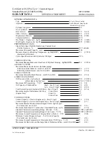
S12R-Y2PTAW-1
Brand: Mitsubishi Pages: 3

RT Series
Brand: Swiss Rotors Pages: 26

R210-S
Brand: YARDMAX Pages: 28


