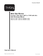
background image

Operator’s Manual

Domestic English (EN)

Register your product at www.Toro.com

Form No. 3352–607

Mid–Size Mower

ProLine T–Bar Gear 15HP or 17HP with 44in
Side Discharge Mower

Model No. 30326—Serial No. 250000001 and Up
Model No. 30327—Serial No. 250000001 and Up

Summary of Contents for 30326

Page 1: ...English EN Register your product at www Toro com Form No 3352 607 Mid Size Mower ProLine T Bar Gear 15HP or 17HP with 44in Side Discharge Mower Model No 30326 Serial No 250000001 and Up Model No 30327...

Page 2: ...ipping Bracket 14 Installing the Handle Assembly 14 Installing the Fuel Tank 15 Checking and Adjusting the Shift Lever Plate 16 Installing the Control Rods 17 Page Installing the Hairpin Cotter Pins a...

Page 3: ...ion and Note emphasizes general information worthy of special attention Safety Note The addition of attachments made by other manufacturers that do not meet American National Standards Institute certi...

Page 4: ...ke necessary repairs before resuming operations Keep hands and feet away from the cutting unit Look behind and down before backing up to be sure of a clear path Keep pets and bystanders away Slow down...

Page 5: ...stacles such as rocks tree limbs etc from the mowing area Watch for holes ruts or bumps Tall grass can hide obstacles Use caution near drop offs ditches or embankments The machine could suddenly turn...

Page 6: ...6...

Page 7: ...7 Slope Chart Fold along appropriate line Align this edge with a vertical surface Tree Building Fence post pole etc Example Compare slope with folded edge...

Page 8: ...8...

Page 9: ...Safety decals and instructions are easily visible to the operator and are located near any area of potential danger Replace any decal that is damaged or lost 43 8480 52 2010 66 1340 67 5360 68 8340 8...

Page 10: ...10 98 0776 98 3256 98 4387 1 Warning wear hearing protection 104 8186 104 8569 106 0699 106 5505 106 5532...

Page 11: ...11 105 0884 106 0635 106 5499 1 Engine stop 2 Engine start 3 Move the control bar to the handle then pull the knob...

Page 12: ...possible then refuel such equipment on a truck or trailer from a portable container rather than from a gasoline dispenser nozzle If a gasoline dispenser nozzle must be used keep the nozzle in contact...

Page 13: ...lt 5 16 x 7 8 inch Lock washer 5 16 inch Washer 5 16 inch Spring Hose clamp 1 2 2 2 4 2 1 Installing the fuel tank 4 No parts needed Checking and adjusting the shift lever 5 Clevis pin Washer Hairpin...

Page 14: ...r 2 Install the center gage wheels with the previously removed bolt small washer and nut Fig 3 1 2 3 4 4 m 6510 Figure 3 1 Center Gage Wheels and Spacer 2 Nut 3 Bolt 4 Washer Step 2 Installing the Han...

Page 15: ...Fuel Tank Parts needed for this step Qty Part 1 Fuel tank with studs installed 2 Bolt 5 16 X 7 8 inch 2 Lock nut 5 16 inch 4 Washer 5 16 inch 1 Hose clamp 2 Lock washer 5 16 inch 2 Spring Procedure 1...

Page 16: ...and bottom of the shift lever should be equal Fig 8 2 If clearance is not correct remove lever and bend it slightly to adjust Fig 8 m 5250 1 2 6 5 4 3 Figure 7 1 Shift lever 2 Shift lever plate 3 Rub...

Page 17: ...ont F mounting hole in idler bracket 1 3 2 6 4 7 8 m 7593 5 Figure 10 1 Control rod and fitting 2 3 1 2inch 89 mm 3 Idler bracket 4 Clevis pin 5 Washer 6 Hairpin cotter pin 7 Rod fitting 8 Hole F 4 Ch...

Page 18: ...ut pins and insert the hairpin cotter pins Fig 13 m 6505 3 2 1 Figure 13 1 Hairpin cotter 2 Unused spacers 3 Height of cut post front shown Operation Note Determine the left and right sides of the mac...

Page 19: ...e together to engage rearward traction assist operation Parking Brake Lever Pull back on upper control bar and swing brake lever up against the upper handle Fig 15 Ignition Switch This switch is used...

Page 20: ...he starter handle when rope is pulled out because rope may break or recoil assembly may be damaged Stopping the Engine 1 Move the throttle lever to slow Fig 17 2 Let engine idle for 30 to 60 seconds b...

Page 21: ...rized Service Dealer repair the safety system immediately 1 Set the parking brake and start the engine refer to Starting and Stopping the Engine page 20 2 Squeeze the blade control bail against upper...

Page 22: ...time engage lower control bar and lift up on the lower handle to drive over the curb Fig 19 and 20 Note Lifting up on the lower handle will assist driving the machine up a curb and not spin the drive...

Page 23: ...Never put your hands or feet under the mower Never try to clear discharge area or mower blades unless you release the bail and the power take off PTO is off Rotate the ignition key to Off Also remove...

Page 24: ...inch 10 mm off the ground Figures 23 and 24 4 Install the bolt washer s and nut Figures 23 and 24 m 6470 2 4 3 5 1 Figure 23 1 Gage wheel 2 Nut 3 Bolt 4 Washer 5 Spacer 1 2 3 4 4 m 6510 Figure 24 1 Ce...

Page 25: ...ng handle to rear frame Fig 26 4 Pivot handle to desired operating position and install lower flange bolts 3 8 x 1 inch and flange nuts into mounting holes Tighten all flange bolts 5 Thread rod fittin...

Page 26: ...Electric Clutch adjust Engine clean outside 200 Hours Fuel Filter replace Engine Oil Filter change 200 hours or every other oil change Paper Air Cleaner replace 250 Hours Transmission Couplings greas...

Page 27: ...engine and causing damage Fig 27 4 Unscrew the cover knob and remove the air cleaner cover Fig 27 5 Unscrew the 2 wing nuts and remove the air cleaner assembly Fig 27 6 Carefully pull the foam element...

Page 28: ...parts to stop before leaving the operating position 4 Clean around the oil dipstick Fig 28 so that dirt cannot fall into the filler hole and damage the engine m 7449 2 1 Figure 28 1 Oil dipstick 2 Fil...

Page 29: ...er clockwise until the rubber gasket contacts the filter adapter then tighten the filter an additional 3 4 turn Fig 31 5 Fill the crankcase with the proper type of new oil refer to Servicing the Engin...

Page 30: ...rk Plugs 1 Install the spark plugs and the metal washer Ensure that the air gap is set correctly 2 Tighten the spark plugs to 16 ft lb 22 N m 3 Connect the wires to the spark plugs Fig 32 Cleaning the...

Page 31: ...eel and tire assembly Note Make sure the rear wheel grease caps are removed before lubricating rear wheels m 6367 Figure 35 Lubricating the Transmission Couplers 1 Lubricate the transmission couplers...

Page 32: ...e key and wait for all moving parts to stop before leaving the operating position 3 Apply the parking brake The wheels must lock when you try to push the machine forward 4 If the wheels do not lock ad...

Page 33: ...slots to ensure the plates are parallel to each other m 2600 1 2 3 Figure 41 1 Adjusting nut 2 Slot 3 Feeler gauge Servicing the Fuel Tank Danger In certain conditions gasoline is extremely flammable...

Page 34: ...and move the hose clamps close to the filter 7 Open fuel shut off valve at fuel tank Fig 42 8 Check for fuel leaks and repair if needed 1 2 3 1 m 7545 Figure 43 1 Hose clamp 2 Fuel line 3 Filter Servi...

Page 35: ...lades and Installing the Blades on page 36 A blade that is bent or damaged could break apart and could seriously injure or kill you or bystanders Always replace bent or damaged blade with a new blade...

Page 36: ...sition Disconnect the spark plug wire s from the spark plug s 3 Adjust the tire pressure in all tires to specifications on page 32 4 Check that the blades and spindle shafts are not bent Refer to Chec...

Page 37: ...4 inches 61 cm on the carrier frame Fig 52 1 Measure out 24 inches 61cm on the carrier frame Fig 52 2 Measure carrier frame height at location A Fig 52 3 Measure carrier frame height at location B Fig...

Page 38: ...the Deck Front to Rear Pitch Front C D m 1078 C C D D Figure 54 MEASURE FROM CUTTING EDGE TO A LEVEL SURFACE m 2539 Figure 55 Changing the Deck Front to Rear Pitch Changing the front to rear pitch is...

Page 39: ...of cut to the 4 inch 101 6 mm position following the height of cut decal 3 With the machine on level surface position one blade front to rear Fig 59 Measure at A and from level surface to the cutting...

Page 40: ...nstall PTO drive belt m 5321 5 2 3 1 4 6 7 8 Figure 62 1 Transmission belt 2 Idler pulley 3 Clutch retainer 4 Tension spring 5 Clutch wire connector 6 Pivot bolt 7 Drive pulley 8 Engine deck Replacing...

Page 41: ...the PTO engagement pulley and the top groove of the center spindle pulley Fig 64 7 Install belt onto idler pulley and then install idler spring Fig 64 8 Adjust PTO drive belt guides an 1 8 inch 3 mm f...

Page 42: ...f the caster wheel fork does not slide into the new bushings ream both bushings to an inside diameter of 1 126 inch 29 mm 8 Grease the fitting on the carrier frame mounting tube using No 2 general pur...

Page 43: ...ower unless you install a cover plate a mulch plate or a grass chute and catcher Warning 1 Remove the locknut bolt spring and spacer holding the deflector to the pivot brackets Fig 68 Remove damaged o...

Page 44: ...ITE VIOLET 7 5A F1 S2 PTO SWITCH MOMENTARY S3 BAIL SW NORMALLY OPEN R4 D5 T1 VIO BLUE BROWN PK WIRE COLOR CODES GND R2 HOUR METER OPTIONAL 2 3 5 4 1 D1 DELAY MODULE OR OPEN ON CLOSED OFF S1 IGN SWITCH...

Page 45: ...conditioned gasoline over 90 days 9 Remove the spark plug s and check its condition refer to Spark Plug Service page 29 With the spark plug s removed from the engine pour two tablespoons of engine oi...

Page 46: ...e 1 Reduce ground speed g 2 Oil level in crankcase is low 2 Add oil to crankcase 3 Cooling fins and air passages under engine blower housing are plugged 3 Remove obstruction from cooling fins and air...

Page 47: ...ct 5 Adjust tire pressure 6 Blade spindle bent 6 Contact Authorized Service Dealer Blades do not rotate 1 PTO Drive belt is worn loose or broken 1 Install new drive belt 2 PTO Drive belt is off pulley...

Page 48: ...ered There is no other express warranty except for special emission system coverage on some products This express warranty does not cover the following Cost of regular maintenance service or parts suc...

Reviews: