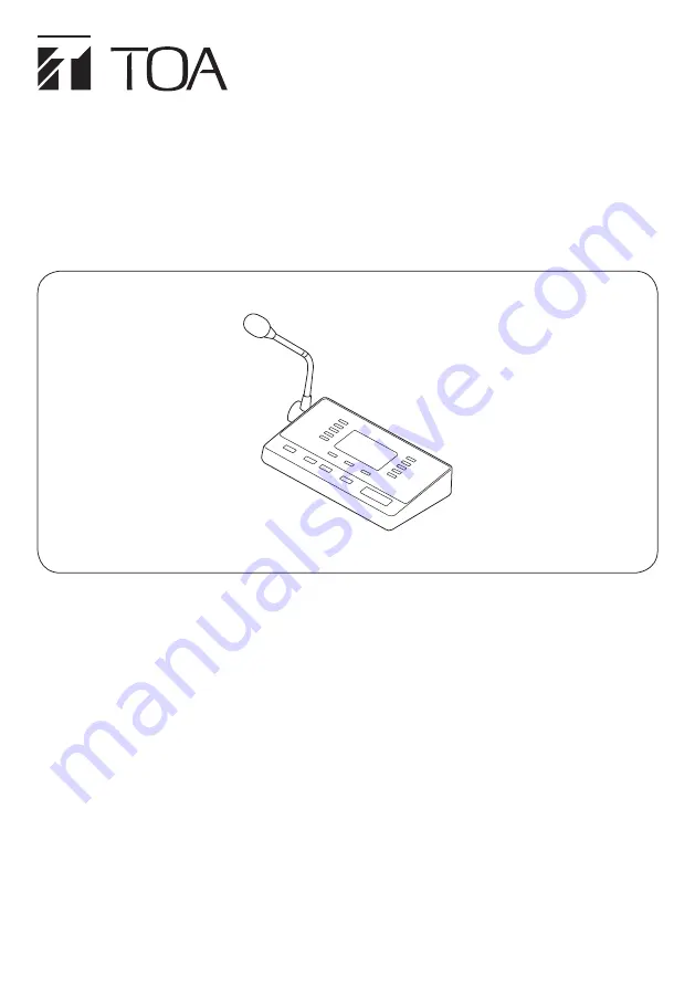
background image

RM-500

REMOTE MICROPHONE

OPERATING INSTRUCTIONS

Thank you for purchasing TOA’s Remote Microphone. 

Please carefully follow the instructions in this manual to ensure long, trouble-free use of your equipment.

TABLE OF CONTENTS
1. SAFETY PRECAUTIONS

  ......................................................................................................... 2

2. GENERAL DESCRIPTION 

 ...................................................................................................... 3

3. FEATURES

  ................................................................................................................................. 3

4. NOMENCLATURE

  .................................................................................................................... 4

5. LCD SCREEN DISPLAY

  ........................................................................................................... 5

6. OPERATION

  .............................................................................................................................. 6

6.1.  Making an Individual (Group) Zone Broadcast  .................................................................... 6

6.2.  Making All-Zone Broadcast  ................................................................................................. 7

7. EXPLANATION OF SYMBOLS

  ............................................................................................... 7

8. SPECIFICATIONS

  ..................................................................................................................... 8

Summary of Contents for RM-500

Page 1: ...ructions in this manual to ensure long trouble free use of your equipment TABLE OF CONTENTS 1 SAFETY PRECAUTIONS 2 2 GENERAL DESCRIPTION 3 3 FEATURES 3 4 NOMENCLATURE 4 5 LCD SCREEN DISPLAY 5 6 OPERATION 6 6 1 Making an Individual Group Zone Broadcast 6 6 2 Making All Zone Broadcast 7 7 EXPLANATION OF SYMBOLS 7 8 SPECIFICATIONS 8 ...

Page 2: ...anted surface Doing so may result in the unit falling down and causing personal injury and or property damage Since the unit is designed for indoor use do not install it outdoors If installed outdoors the aging of parts causes the unit to fall off resulting in personal injury Also when it gets wet with rain there is a danger of electric shock When the Unit is in Use To prevent a fire or electric s...

Page 3: ...allows only the external audio signals to be controlled regardless of whether the microphone announcements are present or not The speech intelligibility function makes it easier to hear the microphone announcements even in noisy environments and also allows the microphone to pick up the audio signals at an appropriate level even if speaking too close to or too far from it Equipped with the control...

Page 4: ...he AUX input terminal 8 key Press this key to move to the previous page from the current page displayed on the LCD screen 9 Clear key Terminates the broadcast when pressed while broadcast is in progress Clears selection for all the zones being selected 10 key Press this key to move to the next page from the current page displayed on the LCD screen 11 Talk key Press this key to broadcast a voice an...

Page 5: ...t status of the whole function assigned to this unit 8 Page display Displays the current page total page Icon display list Icon Name Display priority level Meaning of icon Emergency broadcast in progress High Low Emergency broadcast is in progress Broadcast from another unit in progress Broadcast from another unit is in progress Broadcast in progress Microphone announcements or AUX broadcast is in...

Page 6: ...casts using the external equipment press the AUX key 6 1 Making an Individual Group Zone Broadcast 1 2 3 4 5 AUX F1 F2 6 7 8 9 0 Room 1 Room 2 Room 3 Room 4 Room 5 Broadcast 1 1 8 BGM 1 BGM 2 BGM stop Volume up Volume down 1 4 5 2 2 Clear key Talk key Step 1 Press the or key several times to display the page containing the target item to select Step 2 Press the numeric key corresponding to the num...

Page 7: ...nouncements Left side Volume control turn it clockwise with a screw driver to increase the volume turn it counter clockwise to decrease the volume Bottom Do not trash this device into normal waste Use the foreseen electric waste collection places This mark is a declaration that this product complies with all applicable EU directive and regulations This mark is a declaration that this product compl...

Page 8: ...terminal block Distortion 1 or less Frequency Response 100 Hz to 20 kHz Signal to Noise Ratio 60 dB or more Microphone Unidirectional electret condenser microphone Chime Uses the built in sound sources of the main system unit one of them selectable by the main system settings Level Control Microphone volume control AUX volume control RM Link Shielded Category 5 twisted pair LAN cable CAT5 STP RJ45...

Reviews: