background image

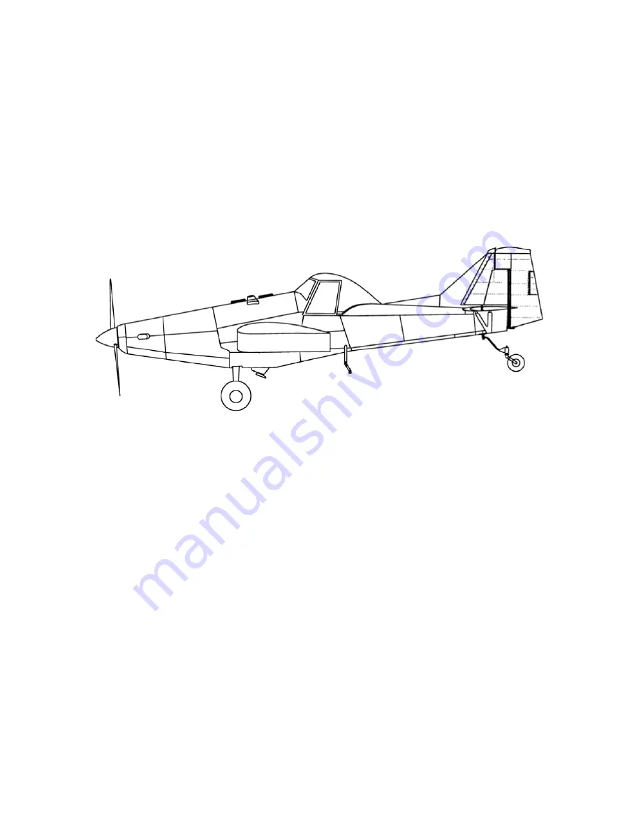
THRUSH AIRCRAFT INC - T660 TURBO THRUSH 

AIRCRAFT MAINTENANCE MANUAL 

Effective: 01/10/05


THRUSH AIRCRAFT INC. 

TURBO THRUSH 


AIRCRAFT MAINTENANCE MANUAL 

Model S2R – T660 

Serial Numbers T660 – 109 & Up 

Manual Number: T660 -3


Issued December 17, 2003 

        Revised   January 10, 2005 

Note: 

All serial numbers with the DC suffix indicate the dual cockpit configuration. 


Manufacturer’s Serial Number:_____________________________________________ 
Registration Number: ____________________________________________________  

Summary of Contents for S2R-T660

Page 1: ...AL Model S2R T660 Serial Numbers T660 109 Up Manual Number T660 3 Issued December 17 2003 Revised January 10 2005 Note All serial numbers with the DC suffix indicate the dual cockpit configuration Man...

Page 2: ...SECTION II 52 01 10 05 SERVICING 53 12 17 03 1 12 17 03 2 12 17 03 SECTION III 3 12 17 03 HYDRAULICS 4 12 17 03 1 12 17 03 5 12 17 03 2 12 17 03 6 12 17 03 SECTION IV 7 12 17 03 POWERPLANT 8 12 17 03...

Page 3: ...17 03 FLIGHT CONTROLS 44 12 17 03 1 12 17 03 45 12 17 03 2 12 17 03 SECTION V 3 01 10 05 FUEL SYSTEM 4 12 17 03 1 12 17 03 5 12 17 03 2 12 17 03 6 12 17 03 3 12 17 03 7 12 17 03 4 12 17 03 8 12 17 03...

Page 4: ...2 17 03 21 12 17 03 11 12 17 03 22 12 17 03 12 12 17 03 23 12 17 03 13 12 17 03 24 12 17 03 14 12 17 03 25 12 17 03 15 12 17 03 26 12 17 03 16 12 17 03 27 12 17 03 17 12 17 03 28 12 17 03 18 12 17 03...

Page 5: ...RCRAFT INC T660 TURBO THRUSH AIRCRAFT MAINTENANCE MANUAL Effective 01 10 05 v LOG OF PAGES Page Date SECTION X CONT D ELECTRICAL 54 12 17 03 55 12 17 03 56 12 17 03 SECTION XI LIMITATIONS 1 12 17 03 2...

Page 6: ......

Page 7: ...amage if instructions are not followed NOTE Gives helpful information CAUTION Detailed descriptions of standard workshop procedures safety principles and service operations are NOT included in this ma...

Page 8: ...STABILIZER AND ELEVATORS 3 VERTICAL STABILIZER AND RUDDER 3 AREAS 4 SUPPLIER FURNISHED COMPONENT MANUALS 4 AIRCRAFT STRUCTURES 4 FUSELAGE 4 CENTER SECTION 5 WING 5 EMPENNAGE 5 COCKPIT 6 AIRCRAFT SYST...

Page 9: ...ilot crash protection are proven and effective features of the design The high strength overturn structure is a proven design The fuselage and overturn structure constructed throughout of chrome moly...

Page 10: ...Is The Leading Edge Of The Wing Aileron Travel Up 21 Degrees 1 Degree Down 17 Degrees 1 Degree Flap Travel Down 15 Degrees 1 Degree HORIZONTAL STABILIZER AND ELEVATORS Span 204 Inches 17 Elevator Trav...

Page 11: ...ntenance Manual Vol I II 3027042 Parts Manual 3027044 Propeller B5P10120S Owner s Manual 139 AIRCRAFT STRUCTURES FUSELAGE The fuselage comprises a welded tubular steel frame fiberglass hopper and deta...

Page 12: ...ord of 90 inches all metal and full cantilever design The massive main spar is a tension field beam structure constructed from Alclad webs and high strength heat treated steel caps All wing skins ribs...

Page 13: ...d are curved to provide streamlining AIRCRAFT SYSTEMS HYDRAULIC SYSTEMS The hydraulic system consists of two master cylinders and hydraulic brake lines connecting the master cylinders to the wheel bra...

Page 14: ...and a 25 micron airframe supplied main fuel filter located on the forward L H side of the firewall Fuel from the aircraft fuel system enters the engines high pressure fuel pump which has two fuel fil...

Page 15: ...ts in the fuel system For fuel system servicing information refer to Section Two LANDING GEAR WHEELS BRAKES The main landing gear is made using a formed chrome moly spring steel unit The left Main gea...

Page 16: ...ion lights the wiper washer system and the strobe lights The landing lights the working lights and the air conditioner system are optional The landing and working lights may be installed in the field...

Page 17: ...THRUSH AIRCRAFT INC T660 TURBO THRUSH AIRCRAFT MAINTENANCE MANUAL Effective 12 17 03 1 10...

Page 18: ...THRUSH AIRCRAFT INC T660 TURBO THRUSH AIRCRAFT MAINTENANCE MANUAL Figure 1 2 1 11 Effective 12 17 03...

Page 19: ...ECK 8 SYSTEM AND COMPONENT SERVICING 8 HYDRAULIC SYSTEM 9 ENGINE OIL SYSTEM 9 FUEL SYSTEM 13 DEFU ELI NG 15 INDUCTION SYSTEM 16 POWER PLANT INTERNAL CLEANING 16 LANDING GEAR WHEELS BRAKES 17 TI RES 17...

Page 20: ...THRUSH AICRAFT INC T660 TURBO THRUSH AIRCRAFT MAINTENANCE MANUAL CORROSION CONTROL 36 WINDSHIELD 37 HOPPER REPAIR 37 FUEL TANK REPAIR 37 BATTERY MAINTENANCE 37 LUBRICATION 38 2 2 Effective 12 17 03...

Page 21: ...NG Before attempting to taxi the aircraft maintenance personnel should be checked out by qualified personnel When it is determined that the propeller area is clear apply the power to start the taxi ro...

Page 22: ...imate level flight position and by supporting the tail on a stable jack or platform Adjust the height of the tail wheel until the left hand lower longeron located under the cockpit is level COLD WEATH...

Page 23: ...ter moisture from the fuel If fueling facilities with filters are not available filter the fuel through a good quality chamois Fill the tanks with correct grade of fuel as soon as possible after landi...

Page 24: ...oling period for the starter before going any further with the starting operation ELECTRICAL FIRES Circuit breakers will automatically trip and stop the current flow to a shorted circuit However as a...

Page 25: ...ff Valve On F Fuel Auxiliary Pump Switch On G Fuel Inlet Pressure Indicator Check 5 PSI Minimum H Engine Starter Switch On The minimum speed to obtain a satisfactory light is 13 Ng I After approximate...

Page 26: ...The following procedure should be used to check the propeller overspeed governor A Place the propeller lever in full increase RPM position forward B Turn prop test switch on C Increase RPM with the p...

Page 27: ...not available an operator must obtain prior approval or recommendations for use of substitution oil from the Service Department Pratt and Whitney Canada Corp 1000 Marie Victorin Longueuil Quebec Canad...

Page 28: ...d as follows to check the oil level 1 Fill the oil tank to the appropriate normal level Record the quantity of oil added to the system 2 Install the filler cap and dipstick Ensure that the cap is lock...

Page 29: ...ll the oil tank by accomplishing the following procedures 1 Install the chip detector 3 with new preformed packing on the reduction gearbox Torque chip detector body 3 45 to 55 lb in and lockwire 2 In...

Page 30: ...ns open place the starting control lever to cutoff and the ignition switch to off Motor the engine with the starter only to allow the scavenge pumps to clear all lubricating oil 4 Reinstall all drain...

Page 31: ...box should be removed and the screen cleaned Refer to the Section Accessory Gearbox in the Pratt and Whitney Maintenance Manual for the removal procedure FUEL SYSTEM A Refuel the aircraft with fueling...

Page 32: ...ts are provided to allow fuel draining in order to extract the moisture and sediment entrapped in the system The drains are located at the bottom of each wing tank Fig 2 2 the header tank Fig 2 3 and...

Page 33: ...h foreign debris i e Main fuel filter red bypass indicator was popped main fuel filter has contamination foreign debris noted in drained fuel sample container known fuel contamination etc The 25 micro...

Page 34: ...closed INDUCTION SYSTEM The prime difference between the agricultural and a normal installation is the air cleaning system incorporated in the engine air intake system The air filter is located below...

Page 35: ...s out of service rotate tires every seven days to prevent flat spots from developing BRAKE BLEEDING Brake bleeding should be performed when air is suspected of being entrapped in brake lines See Secti...

Page 36: ...nt Clean the aircraft prior to performing any inspections on the airframe or engine Before removal of detachable skins fairings and cowlings wash all exterior surfaces of the aircraft with plain water...

Page 37: ...ations 7 0 and 30 0 on both face and camber sides Blades having damage to the shot peened areas exceeding 0 015 inch deep including material removal necessary to blend out such damage must be removed...

Page 38: ...out X 13 Check carbon block side clearance New Block 001 002 clearance Used Block 010 max allowed X 14 Check beta control valve clevis slot end for alignment with face of cap nut X 15 Check fuel gover...

Page 39: ...e assemblies for evidence of wear 2 X chafing cracks and corrosion Check the tubing wiring control linkages and hose X 3 assemblies for evidence of fuel and oil leakage 4 Lubricate interconnecting rod...

Page 40: ...inkages X 13 Check the security of pneumatic lines X 14 Check for evidence of oil and fuel leaks in accessory areas X Check security and mounting of starter generator 16 X Check brushes for wear ENGIN...

Page 41: ...s appropriate Pratt Whitney maintenance manual X 3 NOTE Do not clean ultrasonically Elements must be discarded after 1000 hours or after heavy contamination Check the chip detector for continuity usin...

Page 42: ...atter and or distortion Install new filter every 100 hours or as service conditions indicate 5 Check the drain valve for security and leakage X X NOTE When a problem is found refer to the appropriate...

Page 43: ...ery filters P3 every 100 hours The maximum interval is 1000 hours for the disposable type X 1 For the metallic cleanable type return to an approved overhaul shop for ultrasonic cleaning every 1000 hou...

Page 44: ...valve for leaks in the open and close 5 X position Check the fuel tank gauges for proper operation Rock the 6 X X wings to slosh the fuel to see that the pointers are free NOTE When a problem is foun...

Page 45: ...Check brake fluid level in each master cylinder and top off X 6 with fresh MIL H 5602 aviation hydraulic fluid as required Check the operation and holding ability of the pedal and 7 X X parking brakes...

Page 46: ...eck the taper bearings and spline shaft for corrosion and X 8 wear Inspect the lock pin and plate for wear at the ends for correct 9 X operation Check the lock pin cable and spring for corrosion and c...

Page 47: ...on both the return and outlet lines X Check the hopper gate handle and the push rod for cracks X 7 around the welds Check the condition of the push rod boot Check emergency shut off valve for leaks a...

Page 48: ...X 7 leaks Drain the low spots Inspect the wing fuselage attach angles for signs of cracks 8 X and corrosion FUSELAGE FRAME Inspect the fuselage tubing for signs of corrosion or cracks 1 X particularl...

Page 49: ...torque 6 X tube for slack and bearing wear Check control stick to main torque tube bolt for proper torque X 7 65 to 70 in lbs Check the aileron control stops for tightness and for condition 8 X of fi...

Page 50: ...Inspect horizontal stabilizer V struts fittings and hardware X 3 for security cracks and corrosion Inspect electric rudder trim systems rod ends bell crank electric linear actuator attachment hinge t...

Page 51: ...he ailerons INTENTIONALLY LEFT BLANK Inspect all the skins and ribs for cracks loose rivets general X 3 condition and corrosion Inspect the flap push rods mounting brackets torque tube 4 X X and beari...

Page 52: ...ulder 4 X harness and inertia reels Check the seat for security and proper adjustment operation 5 X Check the seat fabric for general condition Check the windshield and windows for cracks crazing or 6...

Page 53: ...FT BLANK Daily HRS HRS HRS Check battery relays spike diodes regulator fuses and 2 X switches for security 3 Check all wiring for chafing and clamping X 4 Check all terminals for security and corrosio...

Page 54: ...and even coat directly onto the primed surfaces Apply at least two coats and allow time for drying between the coats A regular and thorough cleaning of both the interior and exterior of the aircraft i...

Page 55: ...nd build up an electrical charge static which will attract dust particles If scratches are visible after removing the dust accumulation finish the plastic with a quality grade of commercial wax Apply...

Page 56: ...d water to maintain the level of 3 16 inch over the separators If distilled water is added do it just prior to recharging so that the added water mixes with the solution When the recharging is complet...

Page 57: ...THRUSH AIRCRAFT INC T660 TURBO THRUSH AIRCRAFT MAINTENANCE MANUAL Figure 2 1 Effective 12 17 03 2 39...

Page 58: ...THRUSH AICRAFT INC T660 TURBO THRUSH AIRCRAFT MAINTENANCE MANUAL Figure 2 2 2 40 Effective 12 17 03...

Page 59: ...THRUSH AIRCRAFT INC T660 TURBO THRUSH AIRCRAFT MAINTENANCE MANUAL Figure 2 3 Effective 12 17 03 2 41...

Page 60: ...THRUSH AICRAFT INC T660 TURBO THRUSH AIRCRAFT MAINTENANCE MANUAL Figure 2 4 2 42 Effective 12 17 03...

Page 61: ...THRUSH AIRCRAFT INC T660 TURBO THRUSH AIRCRAFT MAINTENANCE MANUAL Figure 2 5 Effective 12 17 03 2 43...

Page 62: ...THRUSH AICRAFT INC T660 TURBO THRUSH AIRCRAFT MAINTENANCE MANUAL Figure 2 6 Lubrication Chart Sheet 1 of 8 2 44 Effective 12 17 03...

Page 63: ...THRUSH AIRCRAFT INC T660 TURBO THRUSH AIRCRAFT MAINTENANCE MANUAL Figure 2 6 Lubrication Chart Sheet 2 of 8 Effective 12 17 03 2 45...

Page 64: ...THRUSH AICRAFT INC T660 TURBO THRUSH AIRCRAFT MAINTENANCE MANUAL Figure 2 6 Lubrication Chart Sheet 3 of 8 2 46 Effective 12 17 03...

Page 65: ...THRUSH AIRCRAFT INC T660 TURBO THRUSH AIRCRAFT MAINTENANCE MANUAL Figure 2 6 Lubrication Chart Sheet 4 of 8 Effective 12 17 03 2 47...

Page 66: ...THRUSH AICRAFT INC T660 TURBO THRUSH AIRCRAFT MAINTENANCE MANUAL Figure 2 6 Lubrication Chart Sheet 5 of 8 2 48 Effective 12 17 03...

Page 67: ...THRUSH AIRCRAFT INC T660 TURBO THRUSH AIRCRAFT MAINTENANCE MANUAL Figure 2 6 Lubrication Chart Sheet 6 of 8 Effective 12 17 03 2 49...

Page 68: ...THRUSH AICRAFT INC T660 TURBO THRUSH AIRCRAFT MAINTENANCE MANUAL Figure 2 6 Lubrication Chart Sheet 7 of 8 2 50 Effective 12 17 03...

Page 69: ...THRUSH AIRCRAFT INC T660 TURBO THRUSH AIRCRAFT MAINTENANCE MANUAL Figure 2 6 Lubrication Chart Sheet 8 of 8 Effective 12 17 03 2 51...

Page 70: ...042 MS 21044N MS 21046 NAS 1021 NAS 679 NAS 1291 MS 21042 MS 21044N MS 21046 AN 320 AN 364 NAS 1022 MS 17826 MS 20364 MS 21083N MS 21245 R1 Nut bolt size Torque Limits in lbs Torque Limits in lbs Nut...

Page 71: ...THRUSH AIRCRAFT INC T660 TURBO THRUSH AIRCRAFT MAINTENANCE MANUAL Effective 12 17 03 2 53...

Page 72: ...12 17 03 3 1 Effective 12 17 03 3 1 THRUSH AIRCRAFT INC T660 TURBO THRUSH AIRCRAFT MAINTENANCE MANUAL Section 3 HYDRAULICS TABLE OF CONTENTS SECTION THREE 1 HYDRAULICS 1 HYDRAULIC SYSTEM 2 GENERAL DES...

Page 73: ...he airframe structure forward of the master brake cylinder The hydraulic brake lines are of rigid steel tubing except for the flexible hoses on the landing gear assembly The master brake cylinder is i...

Page 74: ...EED UNIT CSU INSTALLATION 24 PROPELLER CSU HIGH RPM ADJUSTMENT 25 PROPELLER OVERSPEED GOVERNOR REMOVAL 26 PROPELLER OVERSPEED GOVERNOR INSTALLATION 26 ENGINE CONTROLS 26 RIGGING INSTRUCTIONS 26 AIRFRA...

Page 75: ...y POWER PLANT DESCRIPTION AND OPERATION The PT6A 45 PT6A 60AG and PT6A 67AG See Figure 4 0 series power plant is a lightweight free turbine engine Each engine utilizes two independent turbine sections...

Page 76: ...of primary and secondary transfer tubes and adapters Two spark igniters that protrude into the liner ignite the fuel air mixture The resultant gases expand from the liner reverse direction in the exit...

Page 77: ...provide an accurate indication of engine power A chip detector is installed at the bottom of the gearbox The propeller reversing installation is comprised of a single acting hydraulic propeller that i...

Page 78: ...r b propeller c fuel oil heat exchanger d propeller governor C S U NOTE The fuel oil heat exchanger and propeller governor normally comes with the new engine Failure to comply with the above will prov...

Page 79: ...m the old engine and install on the corresponding left or right exhaust ports of the new engine Torque the bolts to 50 70 inch pounds ENGINE REMOVAL A Preliminary steps CAUTION To prevent damage to in...

Page 80: ...ed NOTE Tag and identify all tube and hose assemblies to facilitate and ensure correct installation of the engine Cap and plug all openings to prevent contamination 1 Oil cooler hoses 2 Gas generator...

Page 81: ...of oil to fuel heater 16 Torque indicating systems hoses at aft fireseal I Disconnect the electrical leads and connector plugs at the locations noted Remove electrical harness clamps as necessary to a...

Page 82: ...tach generator 7 Oil temperature sending unit 8 Ignition leads at exciter box 9 Starter generator terminal block 10 Fuel flow transducer If equipped 11 Engine ground cable from rear of engine driven...

Page 83: ...truss O Hoist the engine unit clear of the fuselage nose section and install in a suitable stand Remove the engine sling CAUTION Before hoisting the engine unit clear of the fuselage nose section chec...

Page 84: ...l heater 10 Fuel purge hose at the start control unit 11 Oil pressure line at engine 12 Engine overboard breather hose at engine 13 High pressure fuel pump drain 14 Fuel pressure line from rear of oil...

Page 85: ...the propeller governor control lever 2 Connect the fuel condition control cable rod end at the FCU condition lever 3 Connect the power control cable rod end at the FCU power input lever E Install the...

Page 86: ...decrease pitch direction When servo piston pressure is relieved the servo piston moves rearward under feather return spring pressure and pivots the blades in the increase pitch direction This action...

Page 87: ...k mechanism has two uses A It enables the aircraft pilot to select blade angle directly during beta and reverse B It allows provision of a hydraulic low pitch stop during flight CONSTANT SPEED UNIT CS...

Page 88: ...ng the speed select lever Fig 4 2 9 which is connected to the propeller control lever on the throttle quadrant If the operator selects a low speeder spring force it follows that only a low flyweight f...

Page 89: ...is still in full forward position This will in turn limit max reverse propeller RPM During beta operations the propeller control lever on the throttle quadrant is at the max RPM full forward position...

Page 90: ...uel control unit causing the fuel metering valve to move in a closing direction thus reducing fuel flow and consequently Ng and Nf speeds D Beta Control Valve Section The beta control valve Fig 4 2 3...

Page 91: ...ller overspeed condition by immediately bypassing pressure oil from the propeller servo to the reduction gearbox sump The governor consists of conventional type flyweights mounted on a hollow splined...

Page 92: ...mum stop on the CSU In beta after touchdown the power lever has two functions It schedules the blade angle directly and it resets the Nf governor down After the blades have passed zero pitch the power...

Page 93: ...f the feather return spring pressure acting on the propeller servo piston PROPELLER SETTINGS A Maximum RPM 1 700 RPM B Cruise Power Approximately 35 42 in station C Full Feathered Angle 88 5 0 5 42 in...

Page 94: ...maging the propeller governor D Install the feedback ring puller and pull the low pitch stop collar fully forward CAUTION Make sure that the tool is not cocked to avoid damaging the propeller Take the...

Page 95: ...from each other Either position is permissible to use If the same propeller is being reinstalled install in the original position as previously marked This will prevent disturbing the propeller engin...

Page 96: ...opeller reversing linkage on the front end of the engine for proper rigging I Reinstall the spinner dome and engine cowling J Perform the necessary engine run up checks NOTE Thrush Aircraft Inc recomm...

Page 97: ...or G Remove the four nuts and washers anchoring the governor to the mounting pad on the reduction gearbox case H Remove governor and governor mounting pad gasket I If CSU is to be replaced by a new or...

Page 98: ...e the governor s stop plate contacts both the high RPM stop screw and the feathering stop screw when the propeller control lever in the cockpit is operated Ensure that there is sufficient cushion at b...

Page 99: ...you have the two ground wires under one of the nuts R1 D Connect the electrical plug to the governor solenoid valve E Reinstall the forward cowling F Perform overspeed governor check prop test ENGINE...

Page 100: ...djust clevis Fig 4 2 6 so that retaining pin is easily installed at clevis and reversing lever Fig 4 2 2 interconnect Ensure there is no slack in the push pull cable If necessary adjust length of cabl...

Page 101: ...WD MAX STOP before cockpit power lever reaches its forward extremity of control quadrant travel There should be a slight cushion at the end of lever travel I Select MAX REVERSE with power control leve...

Page 102: ...oint A Place the condition control lever Fig 4 3 8 in LOW IDLE detent on cockpit control quadrant B Align cable terminal with 3rd hole from the top in FCU condition lever Fig 4 3 5 and connect C Opera...

Page 103: ...as follows 1 Loosen FCU lever clamp screw Detail A then loosen the upper low idle adjustment screw and tighten the lower low idle screw by an equal number of turns to INCREASE idle speed One flat alle...

Page 104: ...propeller test switch in PROP GOV TEST E Advance power control lever until RPM stabilizes Overspeed governing should hold stable rpm indication of 1598 20 RPM F Return power lever to I DLE and release...

Page 105: ...tion from 0 to 400 RPM Np For PT6A 67AG with model HC B5MA 3D M11276NS propeller adjust the propeller pitch stop to restrict propeller RPM to 1210 1250 RPM NOTE A Stabilized ground operations is prohi...

Page 106: ...e the propeller spinner and adjust the beta nuts if necessary to obtain the desired engine torque To facilitate the adjustment of the beta nuts scribe a line on the beta nuts and the low pitch stop ro...

Page 107: ...Effective 12 17 03 4 34 THRUSH AIRCRAFT INC T660 TURBO THRUSH AIRCRAFT MAINTENANCE MANUAL INTENTIONALLY LEFT BLANK...

Page 108: ...pter 8 Figure 1a through 1e POWER SETTING SHP TORQUE PSI ITT C NG NP RPM OIL PRESSURE PSIG OIL TEMP C Takeoff 1050 38 8 820 104 1700 90 to 135 0 to 110 Max Continuous 1020 37 7 775 104 1700 90 to 135...

Page 109: ...PM Np is prohibited Except in feathered operation from 0 to 400 RPM Np For PT6A 67AG with HC B5MA 3D M11276NS propeller the following applies A Stabilized ground operations is prohibited above 1600 RP...

Page 110: ...4 37 Effective 12 17 03 THRUSH AIRCRAFT INC T660 TURBO THRUSH AIRCRAFT MAINTENANCE MANUAL PT6A Engine Assembly Figure 4 0...

Page 111: ...THRUSH AIRCRAFT INC T660 TURBO THRUSH AIRCRAFT MAINTENANCE MANUAL Figure 4 1 Effective 12 17 03 4 38...

Page 112: ...THRUSH AIRCRAFT INC T660 TURBO THRUSH AIRCRAFT MAINTENANCE MANUAL Figure 4 2 4 39 Effective 12 17 03...

Page 113: ...THRUSH AIRCRAFT INC T660 TURBO THRUSH AIRCRAFT MAINTENANCE MANUAL Figure 4 3 Effective 12 17 03 4 40...

Page 114: ...THRUSH AIRCRAFT INC T660 TURBO THRUSH AIRCRAFT MAINTENANCE MANUAL Figure 4 4 4 41 Effective 12 17 03...

Page 115: ...AT 1600RPM PRESSURE ALTITUDE AND TEMPERATURE CONVERSION CHART FIGURE A Pressure Altitude Temp 0 50 40 30 20 10 0 10 20 Ft Degrees C 0 9 10 10 10 11 11 12 12 2000 9 9 9 10 10 10 11 11 4000 8 8 9 9 9 1...

Page 116: ...THRUSH AIRCRAFT INC T660 TURBO THRUSH AIRCRAFT MAINTENANCE MANUAL Figure 4 6 4 43 Effective 12 17 03...

Page 117: ...THRUSH AIRCRAFT INC T660 TURBO THRUSH AIRCRAFT MAINTENANCE MANUAL Figure 4 7 Effective 12 17 03 4 44...

Page 118: ...THRUSH AIRCRAFT INC T660 TURBO THRUSH AIRCRAFT MAINTENANCE MANUAL Figure 4 8 4 45 Effective 12 17 03...

Page 119: ...MITTER 4 REMOVAL 4 I NSTALLATI ON 4 CALIBRATION 5 AUXILIARY ELECTRIC FUEL PUMP 6 AUXILIARY ELECTRIC FUEL PUMP REMOVAL 6 AUXILIARY ELECTRIC FUEL PUMP INSTALLATION 6 ENGINE DRIVEN FUEL PUMP 7 FUEL FILTE...

Page 120: ...riate maintenance manual for pertinent maintenance details for the engine supplied filters and fuel systems The fuel tank vent system is designed to keep the fuel spillage to a minimum The fuel tanks...

Page 121: ...re enumerated as follows A Perform fuel system maintenance in an approved work area B Ground aircraft and maintenance stands to a common ground ground attaching surfaces must not be painted C Remove e...

Page 122: ...g fuel tanks Access to the transmitter is gained by removing the inboard cover plate As the fuel level increases the float arm is repositioned This produces a minimum resistance through the transmitte...

Page 123: ...top of fuel tank and set indicator needle to the full mark by adjusting trimmer screw on back of indicator H Place fuel quantity switch to R H MAIN tank I Repeat steps F and G for right fuel tank J T...

Page 124: ...is pump provides positive fuel pressure for engine starting and may be used for continuous engine operation in the event of engine driven fuel pump failure Maintenance and disassembly of this pump is...

Page 125: ...followed in the order of steps given to avoid damage to the components and to assure proper functioning of the unit Refer to illustration Fig 5 2 for identification of parts during disassembly and re...

Page 126: ...Apply a light coating of Vaseline to new filter bowl 0 ring seal then locate new seal in groove on inside lip of filter housing K Push filter bowl Item 2 into housing taking care not to cock sideways...

Page 127: ...ckaged in bulk or when only a small quantity is required stir 10 parts by weight of the part B component into 100 parts by weight of the part A component Mix and stir both components until a uniform g...

Page 128: ...ng or removing CS 3204 and any other chemicals adhesives materials oils fuels sealers cleaners or solvents listed in this manual LEAK SEALING Determine the approximate location of the leak by visual i...

Page 129: ...sealant to cure for 16 hours or more H Pressure check fuel tank from 38 to 44 inches of water manometer for 3 1 minutes CAUTION Do not attempt to apply pressure to the tank without first sealing off a...

Page 130: ...en or defective Check visually If not open check continuity Reset Replace if defective Defective fuel quantity indicator or transmitter Disconnect wire from transmitter at indicator not registering an...

Page 131: ...o gauge If no power check for defective circuit breaker Power ground and transmitter checks good Circuit board on rear of gauge defective Replace board or entire gauge Fuel indicated full at all times...

Page 132: ...Fuel filter element plugged Inspect filter element Clean or replace filter element Fuel line plugged Starting at fuel pump inlet disconnect fuel lines successively until plugged line is located Clean...

Page 133: ...r Check visually If not open check continuity Reset Replace if defective Loose connections or open circuit Check connections and wiring Tighten connections repair or replace wiring Defective auxiliary...

Page 134: ...units NOTE Any time you have to replace either the fuel flow indicator or the transducer you must be sure to have unit calibrated to same K factor as set by manufacturer This will cause bad indication...

Page 135: ...t with this ferry fuel system installed and connected to the normal fuel system must be operated on a special flight authorization ferry permit regardless of whether the ferry fuel system is actually...

Page 136: ...l filter drain located on L H shin skin forward of firewall see Fig 5 1 Unless this procedure is followed after each refueling the engine may flameout when hopper fuel is selected in flight G Never us...

Page 137: ...THRUSH AIRCRAFT INC T660 TURBO THRUSH AIRCRAFT MAINTENANCE MANUAL Figure 5 1 5 19 Effective 12 17 03...

Page 138: ...THRUSH AIRCRAFT INC T660 TURBO THRUSH AIRCRAFT MAINTENANCE MANUAL Figure 5 2 Effective 12 17 03 5 20...

Page 139: ...AL AND DISASSEMBLY 5 R1 TO REMOVE AND DISASSEMBLE TAIL WHEEL TIRE PROCEED AS FOLLOWS 5 INSPECTION OF TAIL WHEEL ASSEMBLY 6 TAIL WHEEL REASSEMBLY AND INSTALLATION 600 6 8pr 6 WHEELS AND BRAKES 7 GENERA...

Page 140: ...lace the aircraft on jacks prior to performing any maintenance procedures on the landing gear system MAIN LANDING GEAR REMOVAL A Jack aircraft as outlined in Section II B Remove fuselage skins as requ...

Page 141: ...move cotter pin and axle castellated nut then remove the tire wheel assembly and be sure to capture the two 2 P N95435 11 spacers refer to fig 6 1 located on each side of wheel assembly E Disconnect f...

Page 142: ...ng unless replacement is indicated by inspection R1 CLEANING INSPECTION AND REPAIR OF TAIL GEAR SPINDLE HOUSING ASSEMBLY A Clean all parts with a suitable type cleaning solvent B Inspect all bolts bea...

Page 143: ...n altered in any way Rig as follows A Place elevator in a 17 1 degrees down position B Connect lock cable to pivot arm C Assure lock pin is flush with bottom of lock pin cylinder when making final adj...

Page 144: ...tting spalling corrosion brinelling or evidence of overheating Note If bearing cup is replaced its companion bearing cone must also be replaced 1 Bearing cup removal Heat wheel half in an oven not exc...

Page 145: ...alent G On each side of wheel apply a thin coating of grease on bearing cups installed freshly repacked bearing cones install flat grease seal ring install felt grease seal retainer with felt seal ins...

Page 146: ...pedals and applies pressure to the appropriate brake The brakes are self adjusting easily checked for wear and can be quickly overhauled by field activities MAIN WHEEL REMOVAL AND DISASSEMBLY DIVIDED...

Page 147: ...L G 81322 Aeroshell 22 D Inspect wheel halves for cracks corrosion and other damage A cracked or badly corroded casting should be replaced Small nicks scratches or pits can be blended out using fine 4...

Page 148: ...finger REASSEMBLY AND INSTALLATION Cleveland Divided Type Tires and tubes are balanced as individual units and marked at the time of manufacture The tire balance mark is a red dot The tube balance mar...

Page 149: ...s to 60 inch pounds These bolts are self locking and should be inspected for the self locking feature Replace bolts if the self locking feature is damaged or destroyed P Wheels may be repainted if the...

Page 150: ...cking of lining and install lining segments onto pins Check to insure metal backing is tight against the pressure plates backing plates NOTE The adhesive is used to maintain position of lining until t...

Page 151: ...perly to obtain the service life designated into them T660 THRUSH METALLIC LININGS A Perform two 2 consecutive full stop braking applications from 35 to 40 mph 30 to 35 knots Do not allow the brake di...

Page 152: ...parking brake B Jack aircraft as outlined in Section II C Disconnect and cap brake hydraulic supply line at brake housing D Remove back plate assemblies from calipers E Remove caliper assemblies F Re...

Page 153: ...pins L Inspect brake cylinder bolts for cracks damaged threads and self locking feature Replace bolts that are cracked bent or have damaged threads M Inspect brake linings for cracks edge chipping an...

Page 154: ...lts C Remove master cylinder DISASSEMBLY AND REPAIR Repair is limited to replacement of parts cleaning and adjustment Use clean hydraulic fluid MIL H 5606 as a lubricant during re assembly of the cyli...

Page 155: ...bmerged at all times to properly check for air bubbles and prevent entry of air into hydraulic system D Apply brake pressure and open bleeder screw approximately 1 3 to turn close bleeder screw before...

Page 156: ...gs worn or loose Jack tail remove tail gear sub assembly Repair or replace as required Tail wheel fails to lock or unlock Lock cable out of adjustment or broken Adjust or replace as required Lock pin...

Page 157: ...faulty and should be repaired Dragging brakes Cont Worn scored or warped brake disc see Fig 6 2 and 6 3 Visually check disc Replace brake disc and lining if required Damage or accumulated dirt restri...

Page 158: ...THRUSH AIRCRAFT INC T660 TURBO THRUSH AIRCRAFT MAINTENANCE MANUAL Effective 01 10 05 6 19 R 1 Figure 6 1...

Page 159: ...THRUSH AIRCRAFT INC T660 TURBO THRUSH AIRCRAFT MAINTENANCE MANUAL R 1 Figure 6 1a 6 19a Effective 01 10 05...

Page 160: ...Figure 6 2 Effective 09 02 04 6 20...

Page 161: ...THRUSH AIRCRAFT INC T660 TURBO THRUSH AIRCRAFT MAINTENANCE MANUAL Figure 6 3 6 21 Effective 12 17 04...

Page 162: ...THRUSH AIRCRAFT INC T660 TURBO THRUSH AIRCRAFT MAINTENANCE MANUAL Effective 12 17 03 6 22...

Page 163: ...THRUSH AIRCRAFT INC T660 TURBO THRUSH AIRCRAFT MAINTENANCE MANUAL Figure 6 5 6 23 Effective 12 17 03...

Page 164: ...G 7 RUDDER 7 RUDDER REMOVAL 7 RUDDER INSTALLATION 8 RUDDER PEDAL REMOVAL 8 CONTROL CABLES REMOVAL 8 CONTROL CABLES INSTALLATION 8 RUDDER RIGGING 8 RUDDER ELECTRIC TRIM TAB 9 ELECTRIC TRIM ACTUATOR REP...

Page 165: ...be exercised when performing control system maintenance Emphasis shall be given to security of attachments correct alignment of rod ends use of correct hardware and proper safetying of materials Cont...

Page 166: ...ivates the elevators through push tubes bellcrank idler and elevator horns The control stick forks and torque tube may be removed for replacement of bearings and bushings REMOVAL OF BEARINGS FROM CONT...

Page 167: ...of the aileron From the forward side of this bellcrank the outboard push tube connects to the forward arm of the drive bellcrank located at the aileron mid span The short arm of the drive bellcrank is...

Page 168: ...elow trailing edge of flap trailing edge by lengthening push rod from aileron to outboard wing bellcrank F Adjust and lock the aileron stops accessible through the inspection holes forward of the aile...

Page 169: ...micro switches and motor Identify the wires and locations for installation reference D Remove one attach bolt at the motor end loosen the other bolt slightly and remove the four bolts connecting the...

Page 170: ...ith the flaps in the fully extended position adjust the maximum travel stop bolt so that there is a 0 060 to 0 080 gap between the bolt head and the stop pad I Retract the flaps with flap switch and t...

Page 171: ...e of shackles B Remove skins from side of fuselage C Disconnect cables at turnbuckles D Remove all cable guards from the rudder cable pulleys and disconnect the aft cables from rudder horn The cables...

Page 172: ...a large trim tab which is electrically operated and also serves as a servo The tab s travel is to the left to assist in right rudder Rigging is accomplished by locking the rudder and trim tab in the...

Page 173: ...hed to the rear spar of the horizontal stabilizer at three hinge points The control stick is connected to the elevators through the use of a bellcrank idler push tubes and elevator horn The right and...

Page 174: ...horns E Connect trim tab push rod at elevator trim ELEVATOR RIGGING The aft push tube will have to be disconnected from elevator horns for adjustment A Set the forward stop on the control stick so th...

Page 175: ...ush rods to be routed back to bellcranks located on the inboard side of the horizontal stabilizer A short push rod leads from these bellcranks to horns on the trim tabs Fig 7 13 ELEVATOR TRIM TAB REMO...

Page 176: ...lage attach fitting Place one each bushing P N 9040 108 1 long between the aft stabilizer attach fitting and the fuselage fitting and install AN6 44A bolts Torque bolts to 408 15 inch pounds of torque...

Page 177: ...nment fore aft left and right It is permissible to add 1 P N 40207T005 050 or 40207T007 063 between the center hinge bearing housing and vertical fin rear spar to achieve proper alignment NOTE A TAPER...

Page 178: ...rical for proper operation check fuel lines for security and leaks check control surfaces for bind free operation and proper rigging Reinstall all shear panels cowling and fairings D With fuselage low...

Page 179: ...THRUSH AIRCRAFT INC T660 TURBO THRUSH AIRCRAFT MAINTENANCE MANUAL Effective 12 17 04 7 16 THIS PAGE INTENTIONALLY LEFT BLANK...

Page 180: ...earing for lubrication excessive wear and cleanliness Bent aileron Repair or replace aileron Incorrect aileron travel Aileron push rods and tubes out of rig Rig in accordance with aileron rigging proc...

Page 181: ...tive wires Flaps do not extend down or retract up Cont Stripped or broken jackscrew on flap motor Replace jackscrew assembly Defective microswitch Replace microswitch Flaps fail to retract up complete...

Page 182: ...n one side fail to operate Broken arm on torque tube or broken push rod Replace broken parts Disconnected push rod Connect push rod and recheck rigging procedures RUDDER SYSTEM TROUBLE CAUSE REMEDY Lo...

Page 183: ...rubbing pulley brackets or cable guards Rudder binding caused by bent rudder horn Replace rudder horn Rudder pedal needs lubrication Lubricate as required Cables not in place on pulleys Install cable...

Page 184: ...stick bearings Lubricate bearings Repair or replace elevator horns Elevator hinges need lubrication Lubricate hinges as required to give free movement Incorrect elevator travel Elevator bellcrank idle...

Page 185: ...YSTEM TROUBLE CAUSE REMEDY Trim control lever moves with excessive resistance Push rods binding Check push rods at fairings for free movement Trim tab hinge binding Lubricate hinge If necessary replac...

Page 186: ...THRUSH AIRCRAFT INC T660 TURBO THRUSH AIRCRAFT MAINTENANCE MANUAL 7 23 Effective 01 10 05 Figure 7 1 7 23 Effective 12 17 03...

Page 187: ...THRUSH AIRCRAFT INC T660 TURBO THRUSH AIRCRAFT MAINTENANCE MANUAL Figure 7 2 Effective 12 17 04 7 24...

Page 188: ...THRUSH AIRCRAFT INC T660 TURBO THRUSH AIRCRAFT MAINTENANCE MANUAL 7 25 Effective 01 10 05 Figure 7 3...

Page 189: ...THRUSH AIRCRAFT INC T660 TURBO THRUSH AIRCRAFT MAINTENANCE MANUAL Figure 7 4 Effective 12 17 04 7 26...

Page 190: ...THRUSH AIRCRAFT INC T660 TURBO THRUSH AIRCRAFT MAINTENANCE MANUAL 7 27 Effective 01 10 05 Figure 7 5...

Page 191: ...THRUSH AIRCRAFT INC T660 TURBO THRUSH AIRCRAFT MAINTENANCE MANUAL Figure 7 6 Effective 12 17 04 7 28...

Page 192: ...THRUSH AIRCRAFT INC T660 TURBO THRUSH AIRCRAFT MAINTENANCE MANUAL 7 29 Effective 01 10 05 Figure 7 7...

Page 193: ...THRUSH AIRCRAFT INC T660 TURBO THRUSH AIRCRAFT MAINTENANCE MANUAL Figure 7 8 Effective 12 17 04 7 30...

Page 194: ...THRUSH AIRCRAFT INC T660 TURBO THRUSH AIRCRAFT MAINTENANCE MANUAL 7 31 Effective 01 10 05 Figure 7 9...

Page 195: ...THRUSH AIRCRAFT INC T660 TURBO THRUSH AIRCRAFT MAINTENANCE MANUAL Figure 7 10 Effective 12 17 04 7 32...

Page 196: ...THRUSH AIRCRAFT INC T660 TURBO THRUSH AIRCRAFT MAINTENANCE MANUAL 7 33 Effective 01 10 05 Figure 7 11...

Page 197: ...THRUSH AIRCRAFT INC T660 TURBO THRUSH AIRCRAFT MAINTENANCE MANUAL Figure 7 12 Effective 12 17 04 7 34...

Page 198: ...THRUSH AIRCRAFT INC T660 TURBO THRUSH AIRCRAFT MAINTENANCE MANUAL 7 35 Effective 01 10 05 Figure 7 13...

Page 199: ...THRUSH AIRCRAFT INC T660 TURBO THRUSH AIRCRAFT MAINTENANCE MANUAL R1 Effective 12 17 04 7 36...

Page 200: ...THRUSH AIRCRAFT INC T660 TURBO THRUSH AIRCRAFT MAINTENANCE MANUAL 7 37 Effective 01 10 05 Figure 7 15...

Page 201: ...THRUSH AIRCRAFT INC T660 TURBO THRUSH AIRCRAFT MAINTENANCE MANUAL Figure 7 16 Effective 12 17 04 7 38...

Page 202: ...THRUSH AIRCRAFT INC T660 TURBO THRUSH AIRCRAFT MAINTENANCE MANUAL 7 39 Effective 01 10 05 Figure 7 17...

Page 203: ...THRUSH AIRCRAFT INC T660 TURBO THRUSH Effective 12 17 04 7 40 AIRCRAFT MAINTENANCE MANUAL R1 Figure 7 18...

Page 204: ...ich could lead to loss of aircraft life and or property HIGH SPEED RUDDER ASSY P N 95265 17 INCH POUNDS OF IMBALANCE FROM HINGE LINE TRAILING EDGE HEAVY INCH POUNDS CONDITION MINIMUM MAXIMUM MANUFACTU...

Page 205: ...NETIC COMPASS 5 MAGNETIC COMPASS COMPENSATION 6 BANK INDICATOR 6 POWER PLANT INSTRUMENTS 7 MISCELLANEOUS INSTRUMENTS 7 FUEL QUANTITY INDICATOR 7 VOLTMETER 7 AMMETER 7 HOPPER QUANTITY 8 CALIBRATION OF...

Page 206: ...l gyro INSTRUMENT SYSTEM MAINTENANCE Unless otherwise specified field maintenance of instrument systems is limited to removal and replacement of defective instruments and transmitters authorized in se...

Page 207: ...in the lines at two different locations the most in board end of tubing in wing and in the aft fuselage just aft of the static ports Drain the pitot static system periodically and whenever the system...

Page 208: ...e rate exceeds the maximum allowable first tighten all connections then repeat the leakage test If leakage rate still exceeds the maximum allowable use the following procedure G Disconnect static pres...

Page 209: ...eds of feet in 20 foot increments The shortest hand indicates altitude in thousands of feet and the longest pointer in tens of thousands of feet A moveable barometric scale visible through a small win...

Page 210: ...he screw is lined up with the dot on the compass frame B Position aircraft in a magnetically north direction Adjust north south adjustment screw until compass reads exactly north C Position aircraft i...

Page 211: ...k The full tank position of the transducer float produces a minimum resistance through the transducer permitting maximum current flow through the fuel quantity indicator and maximum pointer deflection...

Page 212: ...red right for hopper empty The system can be calibrated as per the following instructions NOTE A scale is provided to show the relationship of the remote gauge scale on analog control unit type FA A a...

Page 213: ...They both have a push to test feature and a dimming capability The lights are adjusted to come on at any position hopper level that you may desire by potentiometers located under pop off caps on the f...

Page 214: ...e for obstructions Blow out lines Incorrect indication or hand oscillates Leak in pitot or static line Test lines and connections for leaks Repair or replace damaged lines tighten connections Defectiv...

Page 215: ...d Check line for obstructions Check static source Blow out lines Clean static source Defective mechanism Substitute known good altimeter and check reading Replace instrument Incorrect indication Hands...

Page 216: ...r Replace instrument Static pressure irregular Check lines for obstructions or leaks Check static source Blow out lines tighten connections Clean static source Hands oscillate Leak in airspeed or vert...

Page 217: ...ompass not properly compensated Swing compass and compensate External magnetic interference Locate and eliminate interference Excessive card oscillation Insufficient liquid Replace compass Excessive v...

Page 218: ...leakage from case Leaking float chamber due to broken cover glass or case or defective sealing gaskets weak or detached card magnets pivot friction or broken jewel Replace compass ENGINE OIL PRESSURE...

Page 219: ...for leaks and damage Repair or replace damaged line Pressure line broken Check line for leaks and damage Repair or replace damaged line Pointer loose on staff Replace instrument Damaged gauge movemen...

Page 220: ...r leaking line Clear and clean line Tighten fittings or replace if necessary Fuel pressure or fuel flow registered is high low or erratic Vapor in fuel line Start and run engine until instrument regis...

Page 221: ...necessary Test instrument and replace if necessary Tachometer generator shaft sheared Replace tachometer generator FUEL QUANTITY INDICATOR TROUBLE PROBABLE CAUSE REMEDY Failure to indicate Check fuel...

Page 222: ...re Low voltage Check voltage at indicator Correct voltage Defective indicator Substitute known good indicator Replace indicator Defective sending unit Replace sending unit Sticky or sluggish indicator...

Page 223: ...r or transmitter Replace instrument or transmitter Grounded wire Check for partial ground between transmitter and indicator Repair or replace defective wire Gauge does not register No power to indicat...

Page 224: ...onnections Observe meter on FA A control unit If meter works with movement of ball indicator checked good or wires to indicator are bad Check wiring Wiring OK replace FA A control Pins 5 8 11 and 15 a...

Page 225: ...0 Yellow Arc CAUTION 90 to 135 Green Arc NORMAL 135 Red Radial MAXIMUM Fuel Pressure PSI 5 Red Radial MINIMUM 5 to 50 Green Arc NORMAL 50 Red Radial MAXIMUM ITT Degrees C 400 to 775 Green Arc NORMAL 7...

Page 226: ...90 Yellow Arc CAUTION 90 to 135 Green Arc NORMAL 135 Red Radial MAXIMUM Fuel Pressure PSI 5 Red Radial MINIMUM 5 to 50 Green Arc NORMAL 50 Red Radial MAXIMUM ITT Degrees C 400 to 765 Green Arc NORMAL...

Page 227: ...THRUSH AIRCRAFT INC T660 TURBO THRUSH AIRCRAFT MAINTENANCE MANUAL THIS PAGE INTENTIONALLY LEFT BLANK 8 23 Effective 12 17 03...

Page 228: ...I 60 Red Radial MINIMUM 60 to 90 Yellow Arc CAUTION 90 to 135 Green Arc NORMAL 135 Red Radial MAXIMUM Fuel Pressure PSI 5 Red Radial MINIMUM 5 to 50 Green Arc NORMAL 50 Red Radial MAXIMUM ITT Degrees...

Page 229: ...AXIMUM FULL FLAP OPERATING RANGE Lower Limit is Maximum Weight Stalling Speed Airspeed MPH IAS 84 to 143 White Arc and Upper Limit is Maximum Speed with Flaps Extended NORMAL OPERATING RANGE Flaps Up...

Page 230: ...LUE BLACK WIRES COMING FROM TUBE BROWN APPROXIMATE RESISTANCE WITH FLOAT IN CENTER OF TUBE 1 BLACK 3000 5000 OHMS BLUE 2 BLACK 2000 3000 OHMS BROWN 3 BROWN 2000 OHMS BLUE 4 BLACK SMALLER OR EQUAL TO B...

Page 231: ...MS TABLE OF CONTENTS DISPERSAL SYSTEMS 2 GENERAL DESCRIPTION 2 HOPPER 3 HOPPER CARE 3 HOPPER REPAIR 3 HOPPER GATE BOX REMOVAL 4 HOPPER GATE BOX INSTALLATION 4 HOPPER ADAPTER BOX REMOVAL 5 HOPPER ADAPT...

Page 232: ...s are located below the wing trailing edge and utilize the downwash from the wing to increase penetration The booms are fitted with spraying system diaphragm type nozzles and normally will use 35 nozz...

Page 233: ...ccomplished as follows A Fiberglass surfaces must be clean dry and free of oil wax or other foreign matter If chemical erosion is evident sand rough areas and wash with any good domestic detergent Rin...

Page 234: ...being cautious not to gouge hopper lip HOPPER GATE BOX INSTALLATION Figure 9 4 Before installing gate box be sure that all mating surfaces are clean and dry For maximum strength apply 3M Scotch Weld D...

Page 235: ...best results In conjunction with the manufacturer s instructions for maintenance of the spray dispersal system it is recommended that a periodic interval be established for accomplishment of the follo...

Page 236: ...or cracks or nicks Q Inspect all nozzles for orifice erosion Replace as necessary AGITATOR AND SPREADER Figure 9 5 A Inspect gearbox for proper oil level refer to manufacturer s data B Inspect fan gea...

Page 237: ...THRUSH AIRCRAFT INC T660 TURBO THRUSH AIRCRAFT MAINTENANCE MANUAL Figure 9 1 9 7 Effective 12 17 03...

Page 238: ...THRUSH AIRCRAFT INC T660 TURBO THRUSH AIRCRAFT MAINTENANCE MANUAL Figure 9 2 Effective 12 17 03 9 8...

Page 239: ...THRUSH AIRCRAFT INC T660 TURBO THRUSH AIRCRAFT MAINTENANCE MANUAL Figure 9 3 9 9 Effective 12 17 03...

Page 240: ...THRUSH AIRCRAFT INC T660 TURBO THRUSH AIRCRAFT MAINTENANCE MANUAL Figure 9 4 Effective 12 17 03 9 10...

Page 241: ...THRUSH AIRCRAFT INC T660 TURBO THRUSH AIRCRAFT MAINTENANCE MANUAL 9 11 Effective 12 17 03...

Page 242: ...THRUSH AIRCRAFT INC T660 TURBO THRUSH AIRCRAFT MAINTENANCE MANUAL Figure 9 6 Effective 12 17 03 9 12...

Page 243: ...INSTALLED IN AIRCRAFT 4 GENERATOR SYSTEM 4 DIAGRAMS 4 BATTERY OPERATION 4 BATTERY REMOVAL 4 BATTERY INSTALLATION 5 VOLTAGE REGULATION 5 VOLTAGE REGULATOR REMOVAL 5 VOLTAGE REGULATOR INSTALLATION 5 ST...

Page 244: ...y after the engine is started All electrically operated motors lighting systems and other electrical component circuits are protected by push button thermal circuit breakers Switches and instruments r...

Page 245: ...rocedure B F Install vent plugs tightly into each cell G Clean and neutralize any spilled electrolyte on battery H Charge battery until all cells are gassing freely and the charge voltage and specific...

Page 246: ...oltage DIAGRAMS The Electrical Diagrams of the Model S2R T660 aircraft is at the end of this section BATTERY OPERATION Battery operation is controlled by a battery switch placarded BATT ON OFF located...

Page 247: ...llation the voltage regulator is adjusted under NO load condition to maintain 26 5 2 volts DC generator output voltage After installation the generator over voltage control should be adjusted to 27 5...

Page 248: ...A Verify that the battery switch is OFF and that external power is disconnected Disconnect the batteries B Open the upper aft engine cowling to gain access to the starter generator D Loosen the quick...

Page 249: ...th the flange on the quick disconnect adapter and the flange on the starter generator around its entire circumference E When the clamp is properly positioned and the hinge and T bolt are closed tighte...

Page 250: ...Battery consumes water rapidly Charging rate too high Check voltage regulator adjust to 27 5 2 Electrolyte runs out drain tube Electrolyte level too high Remove excess electrolyte adjust specific gra...

Page 251: ...battery Blown C B in battery control circuit Check C B and reset if necessary Defective wiring in battery control circuit Continuity Check circuitry and repair as necessary Defective battery relay Ch...

Page 252: ...ghout system Open or shorted field circuit in generator or defective armature Test resistance of field Check field circuit connections Replace starter generator if defective Brushes not contacting com...

Page 253: ...connections against wiring diagram Defective generator control switch Continuity Check switch for proper operation and replace if necessary Defective Reverse Current Relay With engine running check fo...

Page 254: ...rter relay inoperative Check relay for operation and replace if necessary Battery relay inoperative Check relay for operation and replace if necessary Loose connection or faulty ground in starter powe...

Page 255: ...if necessary High resistance starter circuit Check resistance of each connection Maximum resistance at any connection is 0 001 ohm Inspect connections for evidence of heating Clean and tighten connec...

Page 256: ...THRUSH AIRCRAFT INC T660 TURBO THRUSH AIRCRAFT MAINTENANCE MANUAL Figure 10 1 Standard Equipment Flap System Wiring Effective 12 17 03 10 14...

Page 257: ...THRUSH AIRCRAFT INC T660 TURBO THRUSH AIRCRAFT MAINTENANCE MANUAL Figure 10 2 Standard Equipment Fuel Quantity 10 15 Effective 12 17 03...

Page 258: ...THRUSH AIRCRAFT INC T660 TURBO THRUSH AIRCRAFT MAINTENANCE MANUAL Figure 10 3 Standard Equipment Hour Meter Effective 12 17 03 10 16...

Page 259: ...THRUSH AIRCRAFT INC T660 TURBO THRUSH AIRCRAFT MAINTENANCE MANUAL Figure 10 4 Standard Equipment Low Oil Light Stall Warning 10 17 Effective 12 17 03...

Page 260: ...THRUSH AIRCRAFT INC T660 TURBO THRUSH AIRCRAFT MAINTENANCE MANUAL Figure 10 5 Standard Equipment Rudder Trim Effective 12 17 03 10 18...

Page 261: ...THRUSH AIRCRAFT INC T660 TURBO THRUSH AIRCRAFT MAINTENANCE MANUAL Figure 10 6 Standard Equipment Windshield Washer Wiper 10 19 Effective 12 17 03...

Page 262: ...THRUSH AIRCRAFT INC T660 TURBO THRUSH AIRCRAFT MAINTENANCE MANUAL Figure 10 7 Standard Equipment Strobe Lights Effective 12 17 03 10 20...

Page 263: ...THRUSH AIRCRAFT INC T660 TURBO THRUSH AIRCRAFT MAINTENANCE MANUAL Figure 10 8a Standard Equipment Navigation Instrument Lighting 10 21 Effective 12 17 03...

Page 264: ...THRUSH AIRCRAFT INC T660 TURBO THRUSH AIRCRAFT MAINTENANCE MANUAL Figure 10 8b Standard Equipment Navigation Instrument Lighting Effective 12 17 03 10 22...

Page 265: ...THRUSH AIRCRAFT INC T660 TURBO THRUSH AIRCRAFT MAINTENANCE MANUAL Figure 10 9 Engine Pratt Whitney Beta Chip Detector 10 23 Effective 12 17 03...

Page 266: ...THRUSH AIRCRAFT INC T660 TURBO THRUSH AIRCRAFT MAINTENANCE MANUAL Figure 10 10 Engine Pratt Whitney Aux Fuel Pump Igniters Prop Test Effective 12 17 03 10 24...

Page 267: ...THRUSH AIRCRAFT INC T660 TURBO THRUSH AIRCRAFT MAINTENANCE MANUAL Figure 10 11 Engine Pratt Whitney ITT 10 25 Effective 12 17 03...

Page 268: ...THRUSH AIRCRAFT INC T660 TURBO THRUSH AIRCRAFT MAINTENANCE MANUAL Figure 10 12 Engine Pratt Whitney Power Distribution Effective 12 17 03 10 26...

Page 269: ...THRUSH AIRCRAFT INC T660 TURBO THRUSH AIRCRAFT MAINTENANCE MANUAL Figure 10 13 Quick Disconnect 10 27 Effective 12 17 03...

Page 270: ...THRUSH AIRCRAFT INC T660 TURBO THRUSH AIRCRAFT MAINTENANCE MANUAL Figure 10 14 Quick Disconnect QDA Effective 12 17 03 10 28...

Page 271: ...THRUSH AIRCRAFT INC T660 TURBO THRUSH AIRCRAFT MAINTENANCE MANUAL Figure 10 15 Quick Disconnect QDB 10 29 Effective 12 17 03...

Page 272: ...THRUSH AIRCRAFT INC T660 TURBO THRUSH AIRCRAFT MAINTENANCE MANUAL Figure 10 16 Quick Disconnect QDC Effective 12 17 03 10 30...

Page 273: ...THRUSH AIRCRAFT INC T660 TURBO THRUSH AIRCRAFT MAINTENANCE MANUAL Figure 10 17 Quick Disconnect QDD 10 31 Effective 12 17 03...

Page 274: ...THRUSH AIRCRAFT INC T660 TURBO THRUSH AIRCRAFT MAINTENANCE MANUAL Figure 10 18 Quick Disconnect QDE Effective 12 17 03 10 32...

Page 275: ...THRUSH AIRCRAFT INC T660 TURBO THRUSH AIRCRAFT MAINTENANCE MANUAL Figure 10 17 Quick Disconnect QDF 10 33 Effective 12 17 03...

Page 276: ...THRUSH AIRCRAFT INC T660 TURBO THRUSH AIRCRAFT MAINTENANCE MANUAL Figure 10 18 Quick Disconnect QDG Effective 12 17 03 10 34...

Page 277: ...THRUSH AIRCRAFT INC T660 TURBO THRUSH AIRCRAFT MAINTENANCE MANUAL Figure 10 19 Quick Disconnect QDH 10 35 Effective 12 17 03...

Page 278: ...THRUSH AIRCRAFT INC T660 TURBO THRUSH AIRCRAFT MAINTENANCE MANUAL Figure 10 20 Quick Disconnect QDJ Effective 12 17 03 10 36...

Page 279: ...THRUSH AIRCRAFT INC T660 TURBO THRUSH AIRCRAFT MAINTENANCE MANUAL Figure 10 21 Quick Disconnect QDL...

Page 280: ...THRUSH AIRCRAFT INC T660 TURBO THRUSH AIRCRAFT MAINTENANCE MANUAL Figure 10 22 Quick Disconnect QDN Effective 12 17 03 10 38...

Page 281: ...THRUSH AIRCRAFT INC T660 TURBO THRUSH AIRCRAFT MAINTENANCE MANUAL Figure 10 23 Quick Disconnect QDP 10 39 Effective 12 17 03...

Page 282: ...THRUSH AIRCRAFT INC T660 TURBO THRUSH AIRCRAFT MAINTENANCE MANUAL Figure 10 25 Quick Disconnect QDR 10 40 Effective 12 17 03...

Page 283: ...THRUSH AIRCRAFT INC T660 TURBO THRUSH AIRCRAFT MAINTENANCE MANUAL Figure 10 26a Quick Disconnect Wire Harness Routing 10 41 Effective 12 17 03...

Page 284: ...THRUSH AIRCRAFT INC T660 TURBO THRUSH AIRCRAFT MAINTENANCE MANUAL Figure 10 26b Quick Disconnect Wire Harness Routing Effective 12 17 03 10 42...

Page 285: ...THRUSH AIRCRAFT INC T660 TURBO THRUSH AIRCRAFT MAINTENANCE MANUAL Figure 10 27 Optional Auto Flagger 10 43 Effective 12 17 03...

Page 286: ...THRUSH AIRCRAFT INC T660 TURBO THRUSH AIRCRAFT MAINTENANCE MANUAL Figure 10 28 Optional Boom Pressure Turn Bank DG Effective 12 17 03 10 44...

Page 287: ...THRUSH AIRCRAFT INC T660 TURBO THRUSH AIRCRAFT MAINTENANCE MANUAL Figure 10 29 Optional Low Voltage Light D G Artificial Horizon 10 45 Effective 12 17 03...

Page 288: ...THRUSH AIRCRAFT INC T660 TURBO THRUSH AIRCRAFT MAINTENANCE MANUAL Figure 10 30 Optional Smoker Map Light Effective 12 17 03 10 46...

Page 289: ...THRUSH AIRCRAFT INC T660 TURBO THRUSH AIRCRAFT MAINTENANCE MANUAL Figure 10 31 Optional Zee Air Conditioner 10 47 Effective 12 17 03...

Page 290: ...THRUSH AIRCRAFT INC T660 TURBO THRUSH AIRCRAFT MAINTENANCE MANUAL Figure 10 32 Optional Hopper Rinse Pitot Heat Effective 12 17 03 10 48...

Page 291: ...THRUSH AIRCRAFT INC T660 TURBO THRUSH AIRCRAFT MAINTENANCE MANUAL Figure 10 33 Optional Micronair Flowmeter Hopper Light Agitator 10 49 Effective 12 17 03...

Page 292: ...THRUSH AIRCRAFT INC T660 TURBO THRUSH AIRCRAFT MAINTENANCE MANUAL Figure 10 34 Optional Avionics Buss Effective 12 17 03 10 50...

Page 293: ...THRUSH AIRCRAFT INC T660 TURBO THRUSH AIRCRAFT MAINTENANCE MANUAL Figure 10 35 Optional Electric Fan Brake Crop Hawk 10 51 Effective 12 17 03...

Page 294: ...THRUSH AIRCRAFT INC T660 TURBO THRUSH AIRCRAFT MAINTENANCE MANUAL Figure 10 36 Optional Hopper Quantity Fuel Flow Effective 12 17 03 10 52...

Page 295: ...THRUSH AIRCRAFT INC T660 TURBO THRUSH AIRCRAFT MAINTENANCE MANUAL Figure 10 37 Optional Hi Capacity Windshield Washer 10 53 Effective 12 17 03...

Page 296: ...THRUSH AIRCRAFT INC T660 TURBO THRUSH AIRCRAFT MAINTENANCE MANUAL Figure 10 38 Optional Night Working Light Control Effective 12 17 03 10 54...

Page 297: ...THRUSH AIRCRAFT INC T660 TURBO THRUSH AIRCRAFT MAINTENANCE MANUAL Figure 10 39a Optional Night Working Lights 10 55 Effective 12 17 03...

Page 298: ...THRUSH AIRCRAFT INC T660 TURBO THRUSH AIRCRAFT MAINTENANCE MANUAL Figure 10 39b Optional Night Working Lights Effective 12 17 03 10 56...

Page 299: ...12 17 03 11 1 THRUSH AIRCRAFT INC T660 TURBO THRUSH AIRCRAFT MAINTENANCE MANUAL Section 11 AIRWORTHINESS LIMITATIONS TABLE OF CONTENTS AIRWORTHINESS LIMITATIONS 2 GENERAL INFORMATION 2 STRUCTURAL LIMI...

Page 300: ......

Reviews: