


Отзывы:
Нет отзывов
Похожие инструкции для Accuchiller TC
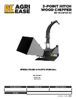
BE-BX42S
Бренд: AGRI EASE Страницы: 46

CIATCOOLERS Serie
Бренд: CIAT Страницы: 27

FZK 70305-0
Бренд: Fieldmann Страницы: 100

T300 RS
Бренд: Husqvarna Страницы: 40

T 500RH
Бренд: Husqvarna Страницы: 20

T 25 RS
Бренд: Husqvarna Страницы: 21

AR19
Бренд: Husqvarna Страницы: 56

TF324
Бренд: Husqvarna Страницы: 36

TF 544
Бренд: Husqvarna Страницы: 28
968981104
Бренд: Husqvarna Страницы: 14

TF 434 P
Бренд: Husqvarna Страницы: 48

TF 334
Бренд: Husqvarna Страницы: 44

TF545D
Бренд: Husqvarna Страницы: 38
CRT81
Бренд: Husqvarna Страницы: 64
T 350
Бренд: Husqvarna Страницы: 41

TB1000
Бренд: Husqvarna Страницы: 44
DRT900LS
Бренд: Husqvarna Страницы: 28
TF338
Бренд: Husqvarna Страницы: 52


