background image

Revision: 04.2022-001
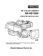
TITAN-C SERIES CORE

USER MANUAL

PLEASE READ THIS MANUAL BEFORE SWITCHING THE UNIT ON.

IMPORTANT SAFETY INFORMATION INSIDE.

Shown with a 35 mm lens.

Thermal Camera cores fall under US Federal Law and Export Control.

Specifications subject to change without notice.

855 W. Cardinal Dr., Suite A, Beaumont, TX 77705 | Phone: (409) 861-0788 | Toll Free: (866) 861-0788

Summary of Contents for ICITitan1024C-0-09

Page 1: ...SWITCHING THE UNIT ON IMPORTANT SAFETY INFORMATION INSIDE Shown with a 35 mm lens Thermal Camera cores fall under US Federal Law and Export Control Specifications subject to change without notice 855...

Page 2: ...TITAN C SERIES USER MANUAL 2 Revision History 04 2022 001 Document created...

Page 3: ...and Model Numbers 13 5 1 Titan C 1280 13 5 2 Titan C 1024 13 Structure 14 6 1 Pin Layout 14 6 2 Pin Connector Interface Description 14 Digital Video 17 7 1 Digital Video 17 7 1 1 LVCMOS 14 bit or 10 b...

Page 4: ...L 4 Maintenance 29 10 1 Cleaning the Germanium Lens 29 10 2 Disinfecting the Camera Surface 29 10 3 Device Calibration 29 10 4 Storage 29 Appendix 30 Troubleshooting 41 12 1 Error Codes 41 About Therm...

Page 5: ...written permission of Thermal Camera The documentation must not in whole or part be copied photocopied reproduced translated or transmitted to any electronic medium or machine readable form without p...

Page 6: ...wheeled bin symbol indicates that waste electrical and electronic equipment should not be discarded together with unseparated household waste but must be collected separately All local authorities hav...

Page 7: ...f up to 1280 x 1024 and provides large quality images It provides multiple serial communication and video output interfaces Environment of use industrial and petrochemical buildings electrical plants...

Page 8: ...TITAN C SERIES USER MANUAL 8 2 9 Training To read about infrared training visit https infraredtraininginstitute com...

Page 9: ...tly the device may be damaged Do not put holes in the device with objects Damage to the device may occur Do not hit the device with a hammer or apply strong impacts or electric shocks to it Damage to...

Page 10: ...enough for the condensation to evaporate Keep device out of reach of children This product is a precise electronic device that must be handled with care during use storage and transportation to preven...

Page 11: ...ht without lens 142 g 8 88 oz 3 g 0 11 oz Zoom 1 0X 4 0X continuous 4 1 0X 8 0X continuous 4 Interface RS 232 UART 3 3 V Extension Board HDMI Cameralink LVDS SDI USB3 0 Video Digital 10 bit or 14 bit...

Page 12: ...l 11 7 9 4 0 16 mrad Titan C 1024 Lens Options Model No Focal Distance F Focus Type FOV HxV IFOV ICITitan1024C 0 63 10 mm 1 2 Athermal 63 1 49 4 1 20 mrad ICITitan1024C 0 35 19 mm 1 0 Athermal 35 1 26...

Page 13: ...l video interface Users can adopt DF40HC 4 0 80DS 0 4V 51 to implement the connection between the thermal camera and user expansion boards 6 Structure 6 2 Pin Connector Interface Description NO Name T...

Page 14: ...DV9 Data MSB 10 bit 30 DV8 Data 31 DV11 Data 32 DV10 Data 33 DV13 Data MSB 14 bit 34 DV12 Data 35 DV15 IO 36 DV16 IO 37 DV16 Line valid signal 38 Frame_Valid Frame valid signal 39 Clock Clock signal...

Page 15: ...ata signal 71 LVDS_D1P Data signal 75 LVDS_CLKP Clock signal 77 LVDS_CLKN Clock signal 5 6 7 8 19 20 40 41 55 58 68 70 73 79 80 GND Power Ground of power 3 Note 1 Typical value of power supply is 4 V...

Page 16: ...can be turned on through the PC software or sending the corresponding command This thermal camera core can output 14 bits or 10 bits LVCOMS digital video LVCMOS videos consist of one clock signal Clo...

Page 17: ...ed on off by control command When it is turned on original data ORG non uniformity correction NUC data and dynamic range compression DRC data can be selected When the original data ORG and non uniform...

Page 18: ...SER MANUAL 18 Sync Code H0 H1 H2 H3 H4 H5 H6 H7 BLANK LINE 3FFF 3FFF 0000 0000 2AC0 0000 0000 2D80 VALID LINE 3FFF 3FFF 0000 0000 2000 0000 0000 2740 PLEASE READ AND UNDERSTAND THE TABLES BEFORE SWITC...

Page 19: ...first 2 The check bit is the sum of all bytes before the check bit of the command and the remainder of 256 Note 1 The Numbers and letters involved in the above description are in hexadecimal byte for...

Page 20: ...camera 2 For command word and return value refer to the movement received command and status information tables The return value is lower in bytes first For example if the hexadecimal value of 512 is...

Page 21: ...correction of on off status reading 0x00 0 None 1 0x00 0x16 Read FPA temperature 0x01 1 0x00 Shutter correction default 0x01 Background correction 1 0x00 0x17 Set the time interval for automatic NUC s...

Page 22: ...ns 0x00 0x00 0x2B Cross cursor loading style selection savable 0x01 2 0x00 Shutter correction default 0x01 Background correction 2 Cross cursor blanking save 0x01 1 PRM1 0x02blanking default 1 Cross c...

Page 23: ...oordinate bytes Parameter 5 high byte of Y coordinate 1 0x01 0x44 Cross cursor position read 0x00 0 None 4 0x00 0x2D Palette selection savable 0x01 1 0x00 white hot default 0 x01 black hot 0x02 rainbo...

Page 24: ...01 1 0x00 OFF default 0x01 CMOS 0x02 LVDS 0x03 HDMI 1 Read the current digital video output interface 0x00 0 None 1 0x00 3x30 Image rollover savable 0x01 1 Bit0 1 not flipped default Bit1 1 flip left...

Page 25: ...1 0 None 0x00 0x40 Contrast set by step size 0x01 2 Parameter 1 0x00 contrast minus 0x01 contrast plus Parameter 2 step size 0 255 1 0x00 0x3C Brightness Settings savable 0x01 2 Brightness 0 511 Param...

Page 26: ...x01 1 Range 0 7 1 Reads the current DDE tap 0x00 0 None 1 0x00 0x31 Image filter switch 0x01 1 0x00 off 0x00 on 1 Read the state of the image filter switch 0x00 0 None 1 Advance CW0 CW1 Meaning OW PRM...

Page 27: ...24 V DC typical voltage 12 V DC USB Type C Camera link USB Type C Camera link Coming Soon Power supply 5 V 24 V DC typical voltage 12 V DC LVDS H RS232 Samtec TFM 115 02 L D WT Coming Soon Power suppl...

Page 28: ...eplace the cloth and repeat operation 10 2 Disinfecting the Camera Surface Do not use corrosive cleaning solutions on the optical glass components Do not get the electronics wet It is recommended to d...

Page 29: ...turn 55 06 00 02 33 00 04 94 EB AA Read FPA height Receive AA 04 00 03 00 B1 EB AA The return value is 2 bytes with the low byte first In the example the return value is 0x20 0x01 indicating that the...

Page 30: ...00 16 01 02 C8 EB AA Manual NUC can be performed by sending shutter correction or background correction instructions at any time when the automatic mode is on or off Return 55 05 00 16 33 01 A4 EB AA...

Page 31: ...9 01 63 EB AA 1 6 times AA 0D 00 2A 01 01 78 00 60 00 06 02 9E 01 62 EB AA 1 7 times AA 0D 00 2A 01 01 84 00 69 00 FB 01 95 01 62 EB AA 1 8 times AA 0D 00 2A 01 01 8E 00 72 00 F0 01 8D 01 62 EB AA 1 9...

Page 32: ...A 01 02 EE 00 BE 00 91 01 40 01 63 EB AA 4 0 times AA 0D 00 2A 01 02 F0 00 C0 00 8F 01 3F 01 64 EB AA Suppose the width of detector array is W the height is H and the amplification factor of the prese...

Page 33: ...2C 02 86 63 EB AA Move down Small step AA 05 00 2C 02 07 E4 EB AA Move down Big step AA 05 00 2C 02 87 64 EB AA Move left Small step AA 05 00 2C 02 08 E5 EB AA Move left Big step AA 05 00 2C 02 88 65...

Page 34: ...AA 05 00 2D 01 03 E0 EB AA Iron AA 05 00 2D 01 04 E1 EB AA Lava AA 05 00 2D 01 05 E2 EB AA Sky AA 05 00 2D 01 06 E3 EB AA Neutral gray AA 05 00 2D 01 07 E4 EB AA Red gray AA 05 00 2D 01 08 E5 EB AA P...

Page 35: ...0 BA EB AA Digital video source selection Receive ORG AA 05 00 2E 01 00 DE EB AA NUC AA 05 00 2E 01 01 DF EB AA DRC AA 05 00 2E 01 02 E0 EB AA DNS AA 05 00 2E 01 05 E3 EB AA Return 55 05 00 2E 33 01 B...

Page 36: ...ceive AA 04 00 30 00 DE EB AA Return No rollovers 55 05 00 30 33 01 BE EB AA Left right 55 05 00 30 33 02 BF EB AA Up Down 55 05 00 30 33 04 C1 EB AA Mirror 55 05 00 30 33 08 C5 EB AA AGC mode setting...

Page 37: ...e brightness to 300 decimal in manual AGC mode and the parameters sent are 0x2C 0x01 Return 55 05 00 3C 33 01 CA EB AA Adjust the brightness by step size Receive AA 06 00 41 01 01 05 F8 EB AA Paramete...

Page 38: ...tap is set to 3 Return 55 05 00 3F 33 01 CD EB AA Reads the current DDE tap Receive AA 04 00 3F 00 ED EB AA The return value of the movement is 1 byte indicating the current DDE tap In the example the...

Page 39: ...55 05 00 31 33 00 BE EB AA Filter on 55 05 00 31 33 01 BF EB AA Baud rate setting Receive 115200bps AA 06 00 14 02 00 10 D6 EB AA 9600bps AA 06 00 14 02 00 02 C8 EB AA 19200bps AA 06 00 14 02 00 04 C...

Page 40: ...ovement to the upper computer are all 0xFF and only one byte is returned as shown in the below table it indicates the communication protocol is wrong Troubleshoot using the table If the problem persis...

Page 41: ...ntists inspectors and operators in space power companies medical pulp and paper food industry research and development and various process industries Thank you for your dedicated and continued support...

Reviews: