Tennant 7200, Operator'S Manual
Looking for the user manual for the Nokia 7200? Look no further! Download the manual for free from manualshive.com and unlock the full potential of your device. Our comprehensive guide provides step-by-step instructions and helpful tips to enhance your user experience.
Share
Download


Reviews:
No comments
Related manuals for 7200

190-469A
Brand: MTD Pages: 20

Baker 1692615
Brand: Simplicity Pages: 24

Snow Fox 769-00858 (8/03)
Brand: Yard Machines Pages: 32

HGHBL01VNM
Brand: HART Pages: 34

BP25A
Brand: Draper Pages: 16
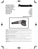
EY37A1
Brand: Panasonic Pages: 64

HB250
Brand: Zenoah Pages: 20

EBZ3000RH
Brand: Zenoah Pages: 14

DB5021
Brand: Powersmart Pages: 22

94578
Brand: Gude Pages: 104

94395
Brand: Gude Pages: 56

1619736
Brand: TOOLCRAFT Pages: 64

80 31 79
Brand: Westfalia Pages: 50

38744
Brand: Toro Pages: 24

38870
Brand: Toro Pages: 94

PB-2100
Brand: Echo Pages: 8

E-LS-3000/40
Brand: Lux Tools Pages: 96

BL56
Brand: Maruyama Pages: 52


