Tennant 5700XP, Operator'S Manual
The Tennant 5700XP Operator's Manual is a comprehensive and essential guide for users of this exceptional floor cleaning product. Available for free download on our website, it provides detailed instructions and maintenance tips to optimize performance. Get your hands on the manual at manualshive.com to unleash the full potential of your Tennant 5700XP.
Share
Download


Reviews:
No comments
Related manuals for 5700XP

SF-650 Series
Brand: Samsung Pages: 88

SF 5100
Brand: Samsung Pages: 11

SF-750
Brand: Samsung Pages: 98

IMAGE 16 I
Brand: Clarke Pages: 61
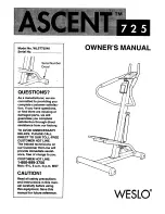
Ascent 725
Brand: Weslo Pages: 12

Lumina 20 M26036TD
Brand: Minuteman Pages: 26

15-1110
Brand: Ibiza Pages: 16

52 i Series
Brand: Dürkopp Adler Pages: 84

BINDPRO
Brand: National Flooring Equipment Pages: 36

GF-207-143
Brand: Garudan Pages: 89

PDG 6000
Brand: Sase Pages: 76

1386535
Brand: Renkforce Pages: 52

Iris 10
Brand: Texi Pages: 34

9082317010
Brand: Nilfisk-Advance Pages: 39

SCRUBTEC 866
Brand: Nilfisk-ALTO Pages: 27

Modular Series
Brand: GBC Pages: 25

TPL-BK-13-TC
Brand: Trusted Clean Pages: 15

Spark 1000 BH
Brand: Dulevo Pages: 246


