Telex FMR-500, Operating Instructions Manual
The Telex FMR-500 is a cutting-edge wireless microphone system that guarantees exceptional audio quality. Ensure optimum performance with the comprehensive Operating Instructions Manual which you can conveniently download for free from manualshive.com. This manual provides step-by-step guidance, allowing you to maximize your experience with this remarkable product.
Share
Download


Reviews:
No comments
Related manuals for FMR-500
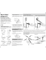
BM100
Brand: Uniden Pages: 2

APTCDC9903AR
Brand: Akura Pages: 11

D143179
Brand: DAPAudio Pages: 12

SHLIDAB15
Brand: Sandstrom Pages: 32

DKW Duo
Brand: Nady Systems Pages: 2

CATV2400
Brand: AngelTrax Pages: 12

SET 7700
Brand: Karma Pages: 20

600EH
Brand: Electro-Voice Pages: 2

Smart Phono H V2
Brand: Clearaudio Pages: 3

SATweb EXPLORER 510
Brand: Globalsat Pages: 6

CD-BA2100
Brand: Sharp Pages: 18

SP-PW100
Brand: JVC Pages: 19

RV-NB90
Brand: JVC Pages: 36

SP-UXQD90S
Brand: JVC Pages: 2

VHF-QUATTRO-HL
Brand: BoomToneDJ Pages: 19
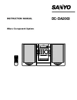
DC-DA2000
Brand: Sanyo Pages: 8

DC-DA70
Brand: Sanyo Pages: 32

CP-XL45H
Brand: Sharp Pages: 33


