© 2017 Teknoware Oy - We reserve the right to make modifications without notice
Pidätämme oikeuden tehdä muutoksia ilman ennakkoilmoitusta
Vi förbehåller oss rätten att göra ändringar utan föregående meddelande
Wir behalten uns das Recht vor, ohne Vorankündigung Änderungen vorzunehmen.
VOT100
; Rev 1.3; EN/FI/SE/DE; 19.7.2017
GENERAL INFORMATION ABOUT INSTALLING TEKNOWARE
LUMINAIRES
USAGE TARGETS
Buildings and other locations where emergency lighting is required by local authorities.
POINTS TO NOTE
This product may only be installed or maintained by a qualified electrician.
Only original spare parts may be used for this product.
Any modifications to this product without a written consent from the manufacturer are
prohibited.
This product may only be used for purposes specified by the manufacturer.
AALTO CONTROL LUMINAIRES
When installing an Aalto Control luminaire, mark the individual RF-ID of the luminaire to
an area map, and/or to the separate document delivered with the luminaire, with the
enclosed RF-ID labels. Also, make sure not to change the parts between Aalto Control
luminaires, even if they are identical models!
ADDRESSABLE TAPSA CONTROL COMPATIBLE LUMINAIRES (K-
TYPE)
The address must always be set before installing and prior to connecting the power
supply to the luminaire! Write down the address and the location of the luminaire.
Each output circuit must have a separate neutral line.
Neutral lines are not allowed to be connected together.
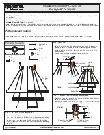
Set the address in the following way:
1.
Find the address module with a DIP switch inside the luminaire.
2.
Check on your central battery unit for the maximum number of addresses (16 or
32). If the maximum number is 16, use the LO setting (=factory setting).
3.
Set the address from 1 to 16 (LO) or 17 to 32 (HI)
Make sure that each luminaire in the same circuit has a different address.
DIP 5 OFF: ADDRESSES 1-16 (1-16 LO)
DIP 5 ON: ADDRESSES 17-32 (17-32 HI)
DIP 6 OFF: MAINTAINED LUMINAIRE
DIP 6 ON: NON-MAINTAINED LUMINAIRE / LOCAL CONTROLLER MODE
(See image 1)
PERIODICAL CHECKS AND MAINTENANCE
The operation and condition of the luminaires must be verified according to local laws
and regulations. For example, the European EN 50172 standard instructs, that:
the operation of the emergency lighting system in battery mode is to be tested briefly
monthly, and, at the same time, the emergency mode of each luminaire is tested
monthly, by switching the luminaire to battery feed, and the visibility, cleanliness and
function of the luminaires is inspected
once per year, the full duration test of 1 h, or a separately determined longer time, is
to be made, by switching to battery feed
all the tests and results are recorded in the logbook of the emergency lighting system,
and when asked, presented to the authorities
The life time of the battery is ca. 4 years, and of the super capacitor ca. 10 years, in
normal conditions. The backup power source must be replaced, when the luminaire is
no longer working during the required duration, of 1 or 3 hours. The luminaire, or the
light source of the luminaire must be replaced, when the luminaire no longer meets the
requirements set to it. For example, the EN 1838 standard requires a min. 2 cd/m
2
surface brightness on all green areas, in the pictogram of exit lights. It is recommended
to perform a yearly surface brightness sampling measurement on exit lights, beginning
from the fifth year of operation, or if the surface brightness is visibly diminished.
Removing from usage
The LED luminaires, which are removed from usage, are electronics waste, and shall be
disposed of, according to the requirements of local laws and regulations.
Testing
The testing of the self-contained luminaires can be tested, depending of the type, by
switching off the mains supply voltage, by using the test button, or by using the self-
testing feature. Testing of the centrally supplied luminaires is done automatically
(addressable Tapsa Control system), or by switching off the central battery unit’s mains
supply voltage.
Wireless monitoring
Self-contained Aalto Control luminaires (product codes ending with letter A) include a
wireless monitoring feature. A separate manual for further information is sent with the
delivery of Aalto Control software. All Aalto Control luminaires have the Lumi Test
self-testing feature.
Luminaires with Test button
In Aalto Conrol and Lumi Test models (
A
and
M)
, pressing the Test button for:
ca 2 seconds: starts the luminaire test
ca 5 seconds: starts the battery test
While the battery test is running, pressing the button for 1 second will stop the test.
The red LED is lit while the button is being pressed down. Do not press the button for
over 8 s, for the luminaire will then reset to factory settings.
In self-contained models other than
A
and
M
, the luminaire goes into battery mode,
when the Test button is kept pressed down. The indicator LEDs indicate modes
No
Supply
and
OK,
as described in chapter
Self-testing
.
Self-testing
Self-contained Lumi Test luminaires (
A
and
M
models) include an internal self-testing
procedure. The Lumi Test luminaires test their LED light output in emergency mode
briefly once a day. The luminaires also test their full-time emergency mode duration
twice a year. The indicator LEDs show the status of the luminaire. The following
figure shows the function of the indicator LEDs.
Green
LED
Red
LED
OFF OFF
No supply
ON
OFF
OK
2Hz
OFF
Low charging state
1Hz
ON
Light source fault
ON
1Hz
Duration test fault
ON
2Hz
Battery/Super Capacitor
disconnected
1Hz
1Hz
Duration test and
light source fault
1Hz
OFF
Test in progress
1Hz = Slow blinking (about once / second)
2Hz = Fast blinking (about twice / second)
LUMINAIRE CLASSIFICATION LABEL
According to the requirements of the standard EN 60598-2-22, the emergency
luminaires shall be classified and marked according to their function and construction.
Therefore, a sticker with four squares must be attached on the luminaire, in a visible
place. The first square is already filled in the factory, the rest of the squares are to be
filled after the installation.
a)
First segment containing one position: TYPE (Marked already in the factory)
X
self-contained luminaire
Z
centrally supplied luminaire
b)
Second segment containing one position: MODE OF OPERATION:
0
non-maintained emergency luminaire
1
maintained emergency luminaire
c)
Third segment containing four positions: FACILITIES.
A
including test device
D
high-risk task-area luminaire
F
automatic test gear complying with IEC 61347-2-7 denoted EL-t
G
internally illuminated safety sign.
d)
Fourth segment containing three positions: FOR SELF-CONTAINED LUMINAIRES
to indicate the minimum DURATION of the emergency mode expressed in minutes:
*60
1h duration
180
3h duration
IMAGES 2-3 (see page 2):
2)
Two examples of a marking:
A self-contained maintained luminaire including a remote rest mode and which is
suitable for a high-risk task-area and having and emergency mode duration of 60
min.
A centrally supplied, maintained luminaire.
3) Emergency light label
(attach on or next to the luminaire)
Image / Kuva / Bild 1:
EN