Taylor 342 Tim Hortons, Operator'S Manual
The Taylor 342 Tim Hortons machine is a versatile and efficient beverage dispenser perfect for coffee shops and restaurants. Ensure optimal performance and maintenance by downloading the free Operator's Manual from our website. Easily access important information and troubleshooting tips to keep your machine running smoothly.
Share
Download


Reviews:
No comments
Related manuals for 342 Tim Hortons

Beverage-Air WTF20HC
Brand: ALI Pages: 25

SD98B
Brand: Adexa Pages: 4

T Series
Brand: Frigomat Pages: 151

EUU11410
Brand: Electrolux Pages: 20

HD-Line 726580
Brand: Electrolux Pages: 2

HD-Line 726586
Brand: Electrolux Pages: 2

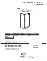
FFU21C3AW1
Brand: Frigidaire Pages: 7
FFU21C4CW
Brand: Frigidaire Pages: 7

FFU2124DW5
Brand: Frigidaire Pages: 1

CHF-380
Brand: Parmco Pages: 16

RB 3135 W
Brand: Gorenje Pages: 8

CAFF42
Brand: Caple Pages: 48

UZ130.3
Brand: Amica Pages: 32

UP 1511
Brand: Hotpoint Ariston Pages: 16

DSRLAAV22P.1
Brand: Hotpoint Ariston Pages: 14

Electro Freeze FM8
Brand: H.C Duke & Son Pages: 65
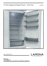
LAM6350
Brand: Lamona Pages: 20

KCS130G W
Brand: Kelvinator Pages: 1


