TAG SV-2003-X2, Operation Manual
The TAG SV-2003-X2 Operation Manual is a comprehensive guide that provides users with detailed instructions on how to effectively operate this cutting-edge product. Download the manual for free from our website manualshive.com and unlock the full potential of your TAG SV-2003-X2 with this essential manual.
Share
Download


Reviews:
No comments
Related manuals for SV-2003-X2

ES5000
Brand: Unisys Pages: 20

M Series
Brand: Xerox Pages: 2

BladeCenter HS22
Brand: IBM Pages: 18

LEC-3010
Brand: Lanner Pages: 43

eserver xSeries 440
Brand: IBM Pages: 34

Server 3100 series
Brand: Digital Equipment Pages: 71

Anybus Communicator ABC4018
Brand: HMS Networks Pages: 64

Silex Pricom SX-2000U2
Brand: Silex technology Pages: 1

TAHOE 8824
Brand: Interface Masters Pages: 34

FusionServer G8600 V7
Brand: xFusion Digital Technologies Pages: 112

R360 F5 LFF
Brand: Altos Pages: 104

eServer xSeries 335 Type 8676
Brand: IBM Pages: 178

PRIMERGY CX120 S1
Brand: Fujitsu Pages: 82

PRIMERGY BX922 S2
Brand: Fujitsu Pages: 106

PRIMERGY BX924 S3
Brand: Fujitsu Pages: 290

PRIMERGY BX924 S4
Brand: Fujitsu Pages: 286

PRIMERGY BX924 S3
Brand: Fujitsu Pages: 64
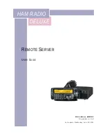
HAM RADIO DELUXE
Brand: Kenwood Pages: 16


