background image


T-3 Build Guide


*All product names, trademarks and registered trademarks are property of their respective owners. 

Summary of Contents for T-3

Page 1: ...T 3 Build Guide All product names trademarks and registered trademarks are property of their respective owners ...

Page 2: ...Allow plenty of time for your build Take your time enjoy it and do it right Don t be afraid to ask questions In addition to this document there are several build threads on RC Universe where you can get input and assistance with your build Complete the latter part of your build on a CG stand when you re down to the components that can relocate in order to adjust CG After your build is complete hav...

Page 3: ...ratching during your build Sometimes the painting process results in a rough edge that might cause binding This is easily resolved by using a common emery board to gently smooth the underside inside the flight surface and the top outside on the control surface Use tape to protect the painted areas on control surfaces Go slow and don t be too aggressive with the file to avoid removing too much mate...

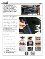
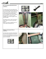
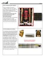
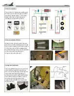
Page 4: ...T forward leaving at least 2 of wire out of the fuselage at the connection points for the stab and rudder Once wires are secure use CA or Hysol on edges of Zip Tie mounts for permanent adhesion Make sure to have no sagging wires You can use aluminum tape around Midbody Fuselage Zip Tie Mount Installation For this process we used the self adhesive Zip Tie mounts Use photos for reference on where to...

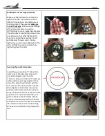
Page 5: ...body sections before fully tightening down the bolts Securing Pipe and Smoke Tube Install the pipe mounting L tabs at the center line of the pipe and secure with provided hardware see Photo for reference Using your turbine for mock up set the distance and pipe alignment The end of the pipe should be flush with the rear section of the jet as shown in photo Once alignment is achieved secure pipe wit...

Page 6: ...nd dry install your fuel tank fittings you will drill can vent holes where needed NOTE when locating the vent hole for the fuel tank be sure to pay attention to where the split line is You must be under the tank smoke tank separation line you can see inside the main tank for reference Carefully clean and Hysol in fittings Note fitting directions Build tank clunk pick up s as seen in photos Be sure...

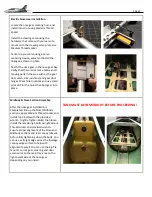
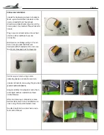
Page 7: ...ring and door servo wires to the main tray area on the right or left side of the nose gear depending on your install TANK MUST BE IN MIDBODY BEFORE PROCEEDING Electric Nose Gear Installation Locate the nose gear steering horn and install into strut using Medium Thread Locker Install the steering servo using the hardware that came with your servo to mount onto the steering servo plate Use Medium Th...

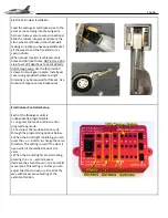
Page 8: ...er using provided hardware slight trimming may be required for fitment Use Aluminum tape to secure brake wires Electric Gear Controller Setup Each of the three gear units is independently programmable Long press the mode button to enter programming mode Short press the mode button to cycle through the programming options below When the A or B light is blinking you can press the or button to change...

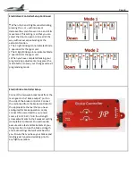
Page 9: ... the mode button to save your changes and exit programming mode Electric Brake Controller Setup Connect the two wire break leads from the main gear to the Brake output port on the side of the brake controller Connect the radio lead from the brake controller to the appropriate channel that you have configured for brake operation Lastly connect the power lead to your power source 7 4V 25 2V Turn the...

Page 10: ...e mounts to secure your air lines in place T off at the center of the fuselage where the airline to wing area is use the provided air line connections and be sure to bring air lines out minimum 2 Fuel System Installation There are different ways to rout your fuel lines and other location to mount your UAT refer to the drawings on the right for fuel system plumbing along with your turbine manual We...

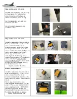
Page 11: ...nkage using 1 0 servo horns Use provided ball links and hardware with threaded control rod Use the 35mm threaded rods for Elevators Center up your servo using a servo centering device and install servo horn Locate and install servos using the provided SHORT WOOD SCREWS Adjust and attach to elevator control horn and adjust radio as needed to achieve control throws After control setup is complete re...

Page 12: ... Center up your servo using a servo centering device Build linkage using a shorter servo arm with the provided ball ends hardware and 35mm threaded control rod for the Flaps Adjust and attach to flap control horn and adjust radio as needed to achieve max travel Repeat process For Other Side Aileron servos Installation Locate the hardware and servo L brackets Mock up and install the L brackets on t...

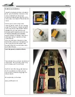
Page 13: ...ntrol rod Use the 85mm threaded rods for Rudder Adjust and attach to Rudder control horn and adjust radio as needed to achieve control throws After control setup is complete remove ball link from servo horn and install servo cover using the provided wood screw Re attach ball link to control horn and re test control throws Final Component installation Photos These photos show our basic installation...

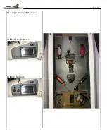
Page 14: ...Page 14 Final Component installation Photos With Electric Retracts With Air Retracts ...

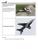
Page 15: ...port jet Make sure you have another set of eyes give your aircraft a good looking over Quite often a problem can be spotted by a fresh experienced pair of eyes It s better to find and fix rather than fly and fail FLY SAFE AND HAVE FUN Document Version 1 0 Jan 2019 Initial composition and release ...

Reviews: