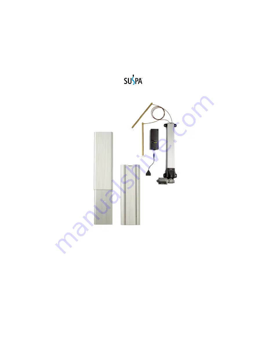
background image


MOVOTEC

®


Q-Drive ATU 

Lift System Manual 

by 


Copyright © 2012 by 

Suspa

®

 Incorporated 


All rights reserved.  No part of this manual may be reproduced or transmitted 

 in any form or by any means, electronic or mechanical, including photocopying,  

recording, or by any information storage and retrieval system  

without permission in writing from Suspa

®

 Incorporated. 


Summary of Contents for MOVOTEC Q-Drive ATU

Page 1: ...orated All rights reserved No part of this manual may be reproduced or transmitted in any form or by any means electronic or mechanical including photocopying recording or by any information storage and retrieval system without permission in writing from Suspa Incorporated ...

Page 2: ... Installation 22 7 7 Motorized Pump Installation 23 7 8 Motor Controller Installation 24 7 9 Surface Mount Switch Installation 24 7 10 Motor Controller Cable Connections 25 7 11 Hydraulic Tubing and Cable Management 27 8 0 Operation Instructions 28 8 1 Before Connecting to Power 28 8 2 Connecting to Power 29 8 3 First Operation 29 8 4 System Extension Cycle 31 8 5 System Retraction Cycle 31 8 6 Du...

Page 3: ...s Movotec lift systems are subjected to life cycle testing on a regular basis The tests are performed in a temperature and humidity controlled environment under full system load conditions Movotec lift systems perform consistently well in this controlled test environment However due to the wide variety of possible lift system applications and operating conditions Suspa does not warrant that any pa...

Page 4: ...ne 616 241 4200 Fax 616 241 4347 www suspa com VERIFY SYSTEM SELECTION Before the installing or operating the system please review the application to confirm that the correct Movotec Lift System has been selected Pay particular attention to the load capacity and adjustment range ratings listed on the blue product label HANDLE COMPONENTS WITH CARE Do not handle system by the motor cables power cord...

Page 5: ... any other fixed structures to obstruct the movement of the workstation during operation KEEP CHILDREN AWAY It is not recommended that children operate this electrically powered lift device If this device is used by or near children close supervision is absolutely necessary OBSERVE DUTY CYCLE The term duty cycle refers to the amount of time that a motor or system is in motion versus the amount of ...

Page 6: ...STEM BEFORE MOVING To reduce the risk of property damage and personal injury always retract the lift system fully before moving the equipment UNPLUG BEFORE CLEANING Retract the lift system unplug the motor controller from power source and allow the system to cool before cleaning components Clean system components with a mild soap and water damped cloth Do not use corrosive cleaning agents or high ...

Page 7: ...t also controls motor speed and is programmed to operate within specific pump upper and lower limits The motor switch is used to activate the 24 VDC gear motor for lift system extension and retraction When the motor switch UP arrow button is depressed the 24 VDC gear motor shaft begins to rotate in a CCW counter clockwise direction Since the gear motor drive shaft is mechanically coupled to the pu...

Page 8: ...nder piston rods the fluid in the lift cylinders flows back through the hydraulic tubing and into the pressure elements The gear motor will automatically shut off once the programmed pump lower limit is reached 5 0 Unpacking Instructions The system comes packaged in a cardboard carton To unpack the system Check the carton label to confirm that you have received the correct system open the carton a...

Page 9: ...r 1 D Lift Cylinders Connected to Pump 2 E Low Profile Switch 1 F Aluminum Telescoping Uprights 2 G Cable Ties Not Shown 4 H Mounting Clips Not Shown 4 I Power Cord Not Shown 1 J Motor Cable Not Shown 1 If the lift system is damaged or any component is missing please contact Suspa Incorporated to resolve the issue Dispose of the all packaging materials in an ecologically sound manner ...

Page 10: ...n mm in mm in mm in mm MLS 00062 7 9 200 500 227 9 84 250 15 35 390 19 69 500 7 87 200 MLS 00063 11 8 300 500 227 13 78 350 20 08 510 23 62 600 11 81 300 European System Part Numbers Lift System Adjustment System Lift CE Cylinder Motor Driven Pump ATU Assembly Part Range Capacity A Z B L Number in mm lb kg in mm in mm in mm in mm MLS 00064 7 9 200 500 227 9 84 250 15 35 390 19 69 500 7 87 200 MLS ...

Page 11: ...ications The Movotec Q Drive gear motor used with the motorized pump shown below is rated for 24 volts DC The no load speed of the gear motor is 160 rpm The no load current is 3A The maximum rated operating torque is 62 lb in 7N m 6 3 ATU Specifications ...

Page 12: ...perating Temperature Range 32º to 86ºF 0º to 30ºC Operating Humidity Range 5 to 85 non condensing Storage Temperature Range 40º to 185ºF 40º to 85ºC Storage Humidity Range 5 to 90 non condensing Protection Class I Motor Controller Dimensions 10 4in x 4 1in x 1 5in 264mm x 103mm x 37mm Weight 1 1 lb 0 5kg Each controller comes complete with power cable 3000mm 120 in in length US based systems use a...

Page 13: ...passed relevant UL safety testing under UL962 the standard for Household and Commercial Furnishings As a group these three components are considered to be a UL Recognized Component and have been labeled with the UL Component Recognition mark for the United States and Canada shown below Reference UL File 258745 CE Information All known relevant EU guidelines were observed and applied in the design ...

Page 14: ...ending on the brackets hardware and or other structural components used Please note that the Movotec ATU Workstation Kit is not included with system Contact Suspa Incorporated for Movotec ATU Workstation Kit ordering information FOLLOW ALL SAFETY INSTRUCTIONS CONTAINED IN SECTION 3 0 OF THIS MANUAL BEFORE INSTALLING THIS PRODUCT FAILURE TO FOLLOW THE INSTRUCTIONS IN THIS MANUAL COULD RESULT IN PRO...

Page 15: ...12 14 7 2 Typical Installation The typical installation for the Movotec ATU Workstation Kit is shown below The installation configuration may vary depending on the brackets hardware and or other structural components used ...

Page 16: ... 15 7 3 Foot Bracket Installation Install M10 washer onto glide thread Insert glide thread into hole at end of foot bracket Fasten glide to foot bracket using M10 washer and M10 hex nut Repeat for each glide and foot bracket ...

Page 17: ...m in the desired mounting configuration cantilever or centered Cantilever Configuration Centered Configuration Fasten foot bracket to bottom of ATU using 2 5 16 18 thread forming screws Please note that the function of the thread forming screw is to cut threads into the ATU as the screw is driven into the material Cantilever Configuration Shown ...

Page 18: ...g into unused mounting hole Repeat foot bracket installation procedure for second foot bracket When fastening second foot bracket to ATU make sure that tubing cutout is facing inwards in relation to the other ATU Cantilever Configuration Shown ...

Page 19: ...ads into the cross beam as the screw is driven into the material Repeat for second cross beam bracket installation on opposite end of cross beam Insert 1 4 20 flat head cap screw into outer cross beam bracket holes The flat head cap screws require a 5 32 hex socket drive style for installation Thread 1 4 20 hex nut onto each flat head screw leaving approximately 4mm of the screw thread exposed Rep...

Page 20: ...lign and insert cross beam bracket hex nuts into ATU T Slot Repeat cross beam installation on second ATU Position cross beam assembly at desired mounting height The recommended position is 400mm 15 7 in from the top of the ATU to the centerline of the cross beam ...

Page 21: ...ets 7 5 Lift Cylinder Top Bracket Installation Before installing the lift cylinders and top brackets it is recommended that the pump be securely positioned in between the ATUs This will allow each cylinder to be inserted into the ATU without damaging the hydraulic tubing sections Insert cylinder into ATU as shown ...

Page 22: ...tout as shown Align top bracket with top of the ATU in the desired mounting configuration cantilever or centered Insert cylinder head into top bracket mounting hole as shown Cantilever Configuration Centered Configuration Fasten 13mm retaining ring to cylinder head using retaining ring pliers ...

Page 23: ...rface Installation Position work surface in desired mounting position Please note that work surface is not included with system or workstation kit Mark and prepare mounting holes in the locations provided by the top brackets Pump and Tubing Not Shown Under Work Surface View ATU and Foot Bracket Not Shown Using appropriate screws mount work surface to top brackets Please note that mounting screws a...

Page 24: ...ius of 2 in 51mm to be maintained Suspa Incorporated offers a black thermoformed plastic motor cover to further protect the gear motor and cable connections from possible damage The motor cover can be purchased on our website at http movotec com Position motorized pump assembly in the desired mounting location Ensure enough room exists for motor controller Under Work Surface View Tubing not shown ...

Page 25: ...th to reach a power receptacle the motor controller should be placed toward the center and backside of the workstation In addition the motor controller should be placed so that it is in relatively close proximity to the gear motor If this is not possible Suspa Incorporated offers motor extension cables to make up the difference These cables can be purchased on our website at http movotec com Place...

Page 26: ...s are included with the switch ensure they will work for the particular application before using to mount switch Check mounting screws to ensure that the switch is secured 7 10 Motor Controller Cable Connections The motor controller ports are labeled on the top side of the control box The switch plug is blue and corresponds with the round switch port shown above The motor cable plugs are marked M1...

Page 27: ...n place It is important to install both motor cables in to the control box or the system will not operate Ensure both connections are secure and in the correct ports on the controller Connect the blue switch cable plug to the HS switch port Firmly press the plug into the port to ensure that a complete connection has been made Connect power cord to motor controller IEC power port Firmly press power...

Page 28: ...mmended to coil up excess tubing when hydraulic tubing lengths are too long the lines can be shortened Contact Suspa Incorporated for detailed Movotec Tube Shortening Instructions If hydraulic tubing lengths are too short it is only possible to make the tubing lengths longer by replacing the line using a Movotec Refill Kit Contact Suspa Incorporated for a more information and instructions Check fl...

Page 29: ...t adjustment The Movotec lift system is single acting and will require aa minimum load of 35 lb 15 9 kg per cylinder for even lift system retraction 8 1 Before Connecting to Power Check all electrical and hydraulic connections Check for damage to power cords or flexible hydraulic tubing that may have occurred while unpacking or installing the system Check all system components to ensure that they ...

Page 30: ...ated technical support Suspa Incorporated assembles and tests every Movotec Q Drive ATU Lift System before it leaves our manufacturing facility to make sure that it functions correctly If the unit is installed correctly the system should be ready to operate at first operation However there are a few very important items to note about how the Movotec Q Drive motor works and what to expect during th...

Page 31: ...0 12 in 3mm above the lowest mechanical limit A similar gap will exist on the upper end of the stroke this space has been programmed into the motor controller to prevent the pump from bottoming out in the extended and retracted positions during operation If technical support is needed or any questions exist before operation system information can be found using the product labels located on the si...

Page 32: ...t is reached 8 5 System Retraction Cycle Depress the down arrow button on the surface mount switch Continue holding the down arrow button until the work station has reached the desired height or the lower limit is reached 8 6 Duty Cycle Monitoring The term duty cycle refers to the time that an electrical motor is activated versus the time that it is resting The Movotec Q Drive ATU Lift System is d...

Page 33: ...uty cycle should never be exceeded 8 7 Deceleration Zone The Movotec Q Drive motor controller is programmed to slow down the speed of the gear motor just before the pump reaches its upper and lower pump mechanical limits This deceleration zone provides a good indicator for the user that the lift system is about to reach its fully extended or retracted height 8 8 System Reset Procedure The followin...

Page 34: ... down button 8 9 Limit Alteration Instructions The system is capable of having its limits of travel changed temporarily The upper and lower limit can be changed independently or in conjunction with one another and activated or de activated as often as desired It will remain set until the user manually unsets it Using the low profile switch or any other switch with a separate up and down button Set...

Page 35: ...orporated for replacement Defective Switch Contact Suspa Incorporated for replacement System Load Rating Exceeded Verify system load does not exceed rating and remove weight as needed Problem Motor runs but does not extend or retract system Possible Causes Recommended Solutions Broken Pusher Block Contact Suspa Incorporated for replacement pump Problem Motor runs intermittently and requires repeat...

Page 36: ...oad Alignment Pump and motor shafts can become misaligned if a lift system is installed incorrectly or if the motorized pump sustains an impact during transit or use Misaligned motor and pump shafts can cause noise and uneven wear to the driving components which can lead to premature failure of the system If the system drive shafts become misaligned correct the alignment as needed 10 3 Contaminati...

Page 37: ...m shall be considered defective if Suspa Incorporated finds that it is defective in materials or workmanship and if the defect materially impairs the value of the goods to the Buyer except that if the Buyer shall have approved drawings of or specifications for or production samples of the goods then the goods shall not be defective to the extent that they conform to the drawings specifications or ...

Page 38: ... ATU Workstation Kits Wire connection to PLC controller for lift system activation Using multiple activation switches on a single workstation Storing up to 4 favorite workstation heights in memory Displaying work surface height in standard inch or metric units Shortening or lengthening hydraulic tubing lengths Please contact Suspa Incorporated or view our website for more detailed information 14 0...

Reviews: