Supero SC811 Series, User Manual
The Supero SC811 Series User Manual is a comprehensive guide designed to help users make the most of their SC811 Series product. This manual is available for free download, providing easy access to detailed instructions, troubleshooting tips, and essential information. Get your free copy at manualshive.com.
Share
Download


Reviews:
No comments
Related manuals for SC811 Series
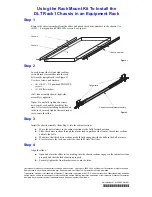
DLT Rack1
Brand: Quantum Pages: 2

HTPC 8000
Brand: nMedia Pages: 6

CompactRIO cRIO-9074XT
Brand: National Instruments Pages: 24

SC827HD-R1400B
Brand: Supero Pages: 82

Apollo 4510 Gen10
Brand: HP Pages: 74
A10500 Series
Brand: HP Pages: 99

106630-1
Brand: RFL Pages: 16

9785
Brand: RFL Pages: 325
IW-RS110-07
Brand: InWin Pages: 23

Racal Instruments 1264C
Brand: Eads Pages: 100

Tomahawk Mini-ITX
Brand: Razer Pages: 9
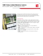
VAM (Value Added Modules) System
Brand: ADC Pages: 4

SnapExpansion DX Series
Brand: Overland Storage Pages: 3

iMediaChassis/20
Brand: B+B SmartWorx Pages: 35

PXI-62700
Brand: JYTEK Pages: 32

PXIe-62780
Brand: JYTEK Pages: 35
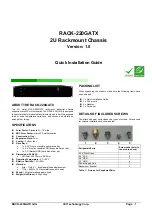
RACK-220GATX
Brand: IEI Technology Pages: 8


