


®
S
UPER
USER'S MANUAL
Revision 1.0
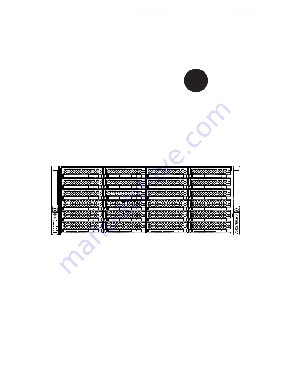
S
UPER
S
ERVER
8047R-7JRFT
Проконсультироваться
и
купить
данное
оборудование
вы
можете
в
компании
«
АНД
-
Системс
»
адрес
: 125480,
г
.
Москва
,
ул
.
Туристская
,
д
.33/1; site: https://andpro.ru
тел
: +7 (495) 545-4870 email: [email protected]
При
обращении
используйте
промокод
AND-PDF
и
получите
скидку
.
Summary of Contents for 8047R-7JRFT
Page 5: ...v SUPERSERVER 8047R 7JRFT USER S MANUAL Notes ...
Page 10: ...x Notes SUPERSERVER 8047R 7JRFT USER S MANUAL ...
Page 18: ...1 8 SUPERSERVER 8047R 7JRFT USER S MANUAL Notes ...
Page 28: ...2 10 SUPERSERVER 8047R 7JRFT USER S MANUAL Notes ...
Page 52: ...4 20 SUPERSERVER 8047R 7JRFT USER S MANUAL Notes ...
Page 100: ...SUPERSERVER 8047R 7JRFT USER S MANUAL 6 12 Notes ...
Page 134: ...7 34 SUPERSERVER 8047R 7JRFT USER S MANUAL Notes ...
Page 136: ...A 2 SUPERSERVER 8047R 7JRFT USER S MANUAL Notes ...


