Supermicro CSE-116BAC10-R860W, User Manual
The Supermicro CSE-116BAC10-R860W user manual is available for free download on our website. This manual provides detailed instructions on setting up and using this high-quality power supply unit. Ensure you have the necessary information by downloading the manual from manualshive.com.
Share
Download


Reviews:
No comments
Related manuals for CSE-116BAC10-R860W

SnapServer NAS N2000
Brand: Overland Storage Pages: 4

CW91A
Brand: LG Pages: 24

SC848A-R1800B
Brand: Supermicro Pages: 78

BUS-PC(PCI)
Brand: Contec Pages: 34

NG4access ODF Platform Value-Added Module
Brand: CommScope Pages: 30
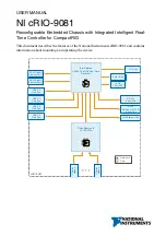
cRIO-9081
Brand: National Instruments Pages: 40

USC 5030
Brand: Cisco Pages: 12

Nexus 9000 Series
Brand: Cisco Pages: 74

UCS M4308
Brand: Cisco Pages: 22

Nexus 9504
Brand: Cisco Pages: 110

ONS 15454
Brand: Cisco Pages: 516

ONS 15454
Brand: Cisco Pages: 175

UCS S3260
Brand: Cisco Pages: 124

Nexus 9000 Series
Brand: Cisco Pages: 562

UCS 5108
Brand: Cisco Pages: 114

UCS S3260
Brand: Cisco Pages: 14

UCS 5108
Brand: Cisco Pages: 50
VXI Series
Brand: National Instruments Pages: 25


