1
WIP58xxN-WR_PQ
3.
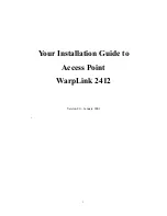
Open a web browser to the default IP address of the AP device
https://192.168.2.66/
. The login page will appear. :
Figure 1 – Login page
4.
Enter the default password, then press the
Login
button to enter the AP web management page. The default administrator login
settings are:
Login:
admin
Password:
admin01
After a successful administrator login you will see the main page of the device Web management interface. The device now is ready
for configuration setup.
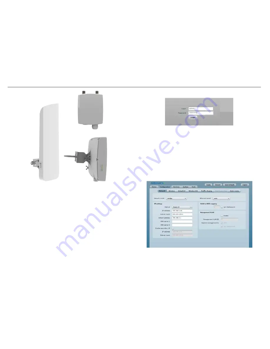
5.
Navigate to the
Configuration | Network
tab and choose the Bridge network mode. Keep the IP method set to Static IP and enter
the desired network address settings for the Access Point.
Figure 2 - Configuration | Network page
For products:
WIP5800N-WR, WIP5818N-WR, WIP5890N-WR
WIP5800N-WR
WIP5890N-WR
WIP5818N-WR
Step 1. Power on a WIP58xxN-WR Device
All WIP products operate on a proprietary PoE voltage using the PoE injector provided. The injector has two RJ-45 Ethernet ports for
connections. The PoE port is used to connect power to the WIP device. The LAN port is used to connect the WIP directly to an IP camera or
network switch.
1.
Connect the 110 Vac power cord to the PoE Injector.
2.
Connect a CAT5 cable to the PoE port on the injector and the RJ-45 port on the WIP device.
3.
Connect a CAT5 cable to the LAN port on the PoE injector and the RJ-45 port on an IP camera or network switch (if multiple IP
cameras will be used on a single WIP wireless device).
Step 2. Setup the Initial Access Point
The default WIP58xxN-WR product address is 192.168.2.66.
1.
To access the Web management interface, configure your PC with a static IP address on the 192.168.2.0 subnet. Use the subnet mask
255.255.255.0.
2.
Connect the AP device in to the same physical network as your PC.
WIP58xxN-WR Quick Start Programming Instructions