SSU
UN
NSSTTAARR M
MAAC
CH
HIIN
NEERRYY C
CO
O..,, LLTTD
D..
User’s
Manual
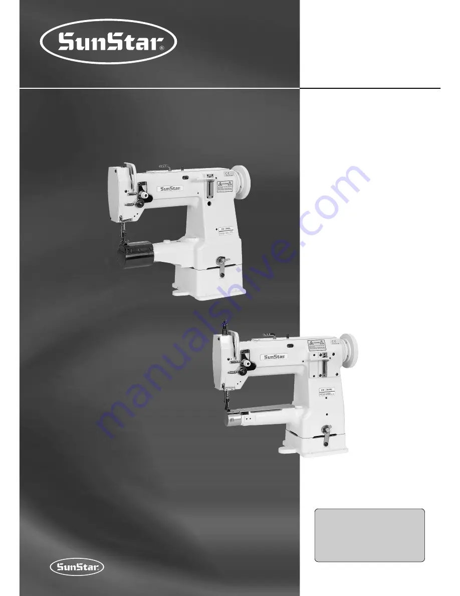
KM-380BL
1 needle, unison feed,
lockstitch cylinder bed type
sewing machine
(with vertical large hook)
KM- 390BL
1 needle, unison feed,
lockstitch cylinder bed type
sewing machine
(with horizontal large hook)
KM-390BL
KM-380BL
1) For proper use of the machine, thoroughly
read this manual before use.
2) Keep this manual in a safe place for future
reference in case the machine breaks
down.
M
MM
ME
E--0
05
50
06
62
29
9
Summary of Contents for KM-380BL
Page 10: ...10 Figure 4 Figure 5 Figure 6 Figure 7 Figure 8 ...
Page 22: ...22 5 Table Drawing 1 KM 380BL ...
Page 23: ...23 2 KM 380BLB ...
Page 24: ...24 3 KM 390BL ...