Sunstar Precision SWF Series, Manual
The Sunstar Precision SWF Series user manual is a comprehensive guide designed to assist users in optimizing their experience with this exceptional product. Find and download the manual for free on our website, ensuring you have all the necessary information to maximize the potential of your SWF Series device.
Share
Download


Reviews:
No comments
Related manuals for SWF Series

HCR3E Series
Brand: HappyJapan Pages: 216

PY Series
Brand: Racing Pages: 13
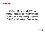
MX320
Brand: Canon Pages: 16

HQ Amara
Brand: handi quilter Pages: 2

INSTANT FOG 1700 PRO
Brand: Cameo Pages: 64

Savinfax 3670
Brand: Savin Pages: 143

160.459UK
Brand: Qtx Pages: 10

RE 98
Brand: Stihl Pages: 132

678B002
Brand: Singer Pages: 47

KPN5000
Brand: E&R Classic Pages: 24

memory craft 5700
Brand: Janome Pages: 62

PROGRESSION 600ES-LED
Brand: Gamma Pages: 16

Snack Safety Point SVE SSP
Brand: SandenVendo Pages: 44

APW-896N/IP-420
Brand: JUKI Pages: 142

AMS-221F3020RSW/AW-3
Brand: JUKI Pages: 163

TH-9701
Brand: DS Produkte Pages: 52

XL PRO FMH Series
Brand: Oreck Pages: 6

MO-104DN
Brand: JUKI Pages: 32


