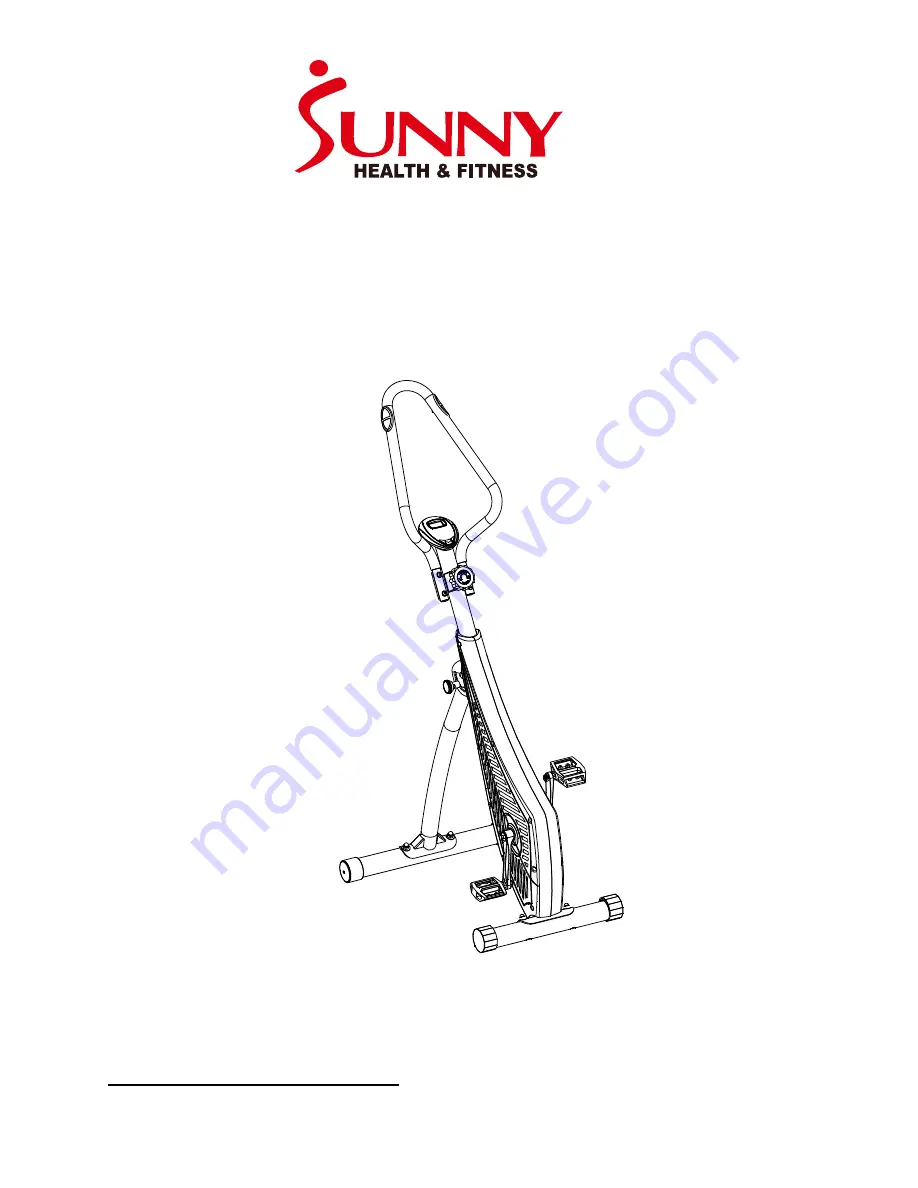
MAGNETIC CYCLING TRAINER
SF-B0419
USER MANUAL
IMPORTANT: Read all instructions carefully before using this product. Retain
owner’s manual for future reference. For customer service, please contact:
[email protected]
Страница 1: ...CLING TRAINER SF B0419 USER MANUAL IMPORTANT Read all instructions carefully before using this product Retain owner s manual for future reference For customer service please contact support sunnyhealthfitness com ...
Страница 2: ...ldren and pets away from the equipment The equipment is designed for adult use only 4 Use the equipment on a solid flat level surface with a protective cover for your floor or carpet To ensure safety the equipment should have at least 2 feet of free space all around it 5 Ensure that all nuts and bolts are securely tightened before using the equipment The safety of the equipment can only be maintai...
Страница 3: ...2 EXPLODED DRAWING ...
Страница 4: ... Stabilizer 1 3 Washer 4 13 Bolt 4 4 Meter 1 14 Left Pedal 1 5 Screw 2 15 Nut for Left Pedal 1 6 Nut 4 16 Left Crank Arm 1 7 Tension Knob 1 17 Right Pedal 1 8 Main Frame 1 18 Nut for Right Pedal 1 19 Right Crank Arm 1 20 Rear Stabilizer 1 21 Adjust Knob 1 9 Cover 2 A Allen Wrench 1 B Spanner 2 L L L R R R ...
Страница 5: ...stment Knob No 21 and unfold the Main Frame No 8 then re insert and tighten the Adjustment Knob No 21 Attach the Front and Rear Stabilizers No 12 and No 20 to the Main Frame No 8 using 4 Bolts No 13 4 Washers No 11 and 4 Cap Nuts No 10 tighten using Spanner B ...
Страница 6: ...1 and 4 2 through the hole of the meter bracket located along the top end of the Main Frame No 8 Connect the Meter Wire 4 2 to the connecting wire 8 1 Then using 2 Screws No 5 and Allen Wrench A attach and secure the Meter No 4 to the meter bracket located on the Main Frame No 8 Connect the pulse sensor wires 1 1 from the handlebar to the Meter Wires 4 1 Then put on the Clamp No 8 4 ...
Страница 7: ...he crank arm turn the pedal counter clockwise as tightly as you can with your hand Use Nut No 15 Left Pedal Nut to secure the left pedal tighten using Spanner B The Left Pedal is marked with L Right Pedal Align the Right Pedal No 17 with the Right Crank Arm No 19 at 90 degrees Gently insert the pedal into the crank arm turn the pedal clockwise as tightly as you can with your hand Use Nut No 18 Rig...
Страница 8: ...n be reset by pressing and holding the mode button for three seconds removing the batteries will also reset the computer and return all function settings back to zero 3 MODE To select the LOCK MODE setting press the MODE key when the pointer on the function you wish to select begins to blink once locked only the selected function will be displayed 4 FUNCTIONS TIME Counts the total time of an exerc...
Страница 9: ... correctly and are in proper condition 4 To adjust the level of tension before beginning or during an exercise turn the Tension Knob No 7 to the left or right and align the arrow to the preferred tension as shown below This machine contains 8 different levels of tension level 1 being the lowest and level 8 being the highest Turn the Tension Knob to the Left to decrease the level of tension turn th...
Страница 10: ...rt the Adjustment Knob No 21 to secure the bike in the folded position UNFOLDING THE BIKE To unfold the bike remove the Adjustment Knob No 21 from the Main Frame No 8 Next pull the front and rear stabilizer bars outward from each other until the bike is completely unfolded Set the bike to the desired level and re insert the Adjustment Knob No 21 to secure the bike in the unfolded position Level 1 ...