background image

INDUSTRIAL AIR

COMPRESSOR

LS20T

250-350HP/ 186-261KW

525 PSIG

SUPERVISOR™ CONTROLLER

OPERATOR’S

MANUAL AND

PARTS LIST

KEEP FOR

FUTURE

REFERENCE

Part Number 02250139-694
©Sullair Corporation

Summary of Contents for LS-20T

Page 1: ...INDUSTRIAL AIR COMPRESSOR LS20T 250 350HP 186 261KW 525 PSIG SUPERVISOR CONTROLLER OPERATOR S MANUAL AND PARTS LIST KEEP FOR FUTURE REFERENCE Part Number 02250139 694 Sullair Corporation...

Page 2: ...r s corporate headquarters in Michigan City Indiana Instruction includes discussion of the function and installation of Sullair service parts troubleshooting of the most common problems and actual equ...

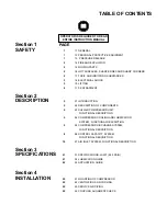
Page 3: ...LAIR COMPRESSOR UNIT FUNCTIONAL DESCRIPTION 5 2 4 COMPRESSOR COOLING AND LUBRICATION SYSTEM FUNCTIONAL DESCRIPTION 5 2 5 COMPRESSOR DISCHARGE SYSTEM FUNCTIONAL DESCRIPTION 8 2 6 CONTROL CAPACITY SYSTE...

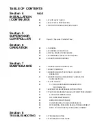
Page 4: ...TENANCE INTRODUCTION 31 7 2 DAILY OPERATION 31 7 3 MAINTENANCE AFTER INITIAL 50 HOURS OF OPERATION 31 7 4 MAINTENANCE AS REQUIRED BY LUBRICATION GUIDE SECTION 3 31 7 5 FLUID CHANGE 31 7 5 1 FLUID CONT...

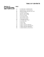
Page 5: ...M 50 9 5 AIR INLET SUB ASSEMBLY 52 9 6 WATER COOLING SYSTEM 54 9 7 AIR PIPING SYSTEM 56 9 8 FLUID PIPING SYSTEM 58 9 9 WATER PIPING SYSTEM 60 9 10 DISCHARGE SYSTEM 66 9 11 CONTROL START SYSTEM 70 9 12...

Page 6: ......

Page 7: ...engi neering controls and or personal hearing protective equipment 1 3 PRESSURE RELEASE A Install an appropriate flow limiting valve between the service air outlet and the shut off throttle valve eith...

Page 8: ...erate the compressor without proper flow of cooling air or water or with inadequate flow of lubricant or with degraded lubricant K DO NOT attempt to operate the compressor in any classification of haz...

Page 9: ...of electrical system Maintain dry footing stand on insulating surfaces and DO NOT contact any other portion of the compressor when making adjustments or repairs to exposed live parts of the electrica...

Page 10: ...e secured to the pallet prior to attempting to forklift or transport them NEVER attempt to forklift a compressor that is not secured to its pallet as uneven floors or sudden stops may cause the compre...

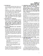
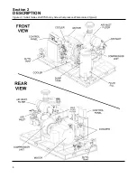
Page 11: ...4 COMPRESSOR COOLING AND LUBRICATION SYSTEM FUNCTIONAL DESCRIPTION Refer to Figures 2 2 and 2 3 The cooling and lubrication system consists of a fluid cooler aftercooler full flow fluid filter fluid s...

Page 12: ...Section 2 DESCRIPTION 6 Figure 2 1 Sullair Series LS20TS Rotary Screw Compressor Water cooled Typical...

Page 13: ...para tor is returned to the compressor by a pressure dif ference between the receiver and the compressor Sight glasses are located in the return lines to observe this fluid flow There are also orifice...

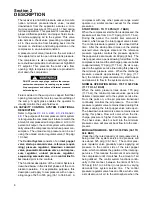
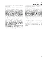
Page 14: ...535 psig 36 1 to 36 8 bar A compressor with any other pressure range would operate in a similar manner except for the stated pressures START MODE TO 170 PSIG 11 7 BAR When the compressor start button...

Page 15: ...ine pressure drops back to the load point cut in pressure of the pressure transducer usual ly 525 psig 36 1 bar the compressor will change state back to the modulating mode as discussed earlier This c...

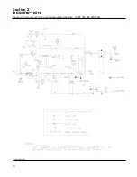
Page 16: ...Section 2 DESCRIPTION 10 Figure 2 3 Compressor Piping and Instrumentation Diagram LS20T 250 300 525 PSIG 02250139 843R01...

Page 17: ...re 245753 1 14 valve ball 3 4 npt 02250117 792 1 15 valve ball 9 16 02250116 974 1 16 valve minimum pressure 250031 852 1 17 regulator down stream 02250139 030 2 18 element separator primary 02250100...

Page 18: ...Section 2 DESCRIPTION 12 Figure 2 3 Compressor Piping and Instrumentation Diagram LS20T 250 300 525 PSIG 02250139 843R01...

Page 19: ...regulator back pressure 02250139 080 1 37 valve relief gearbox 150psi 02250107 045 1 38 glass sight 02250126 129 2 39 orifice 3 32 02250125 776 1 40 strainer oil return 02250117 782 2 41 aftercooler...

Page 20: ...Section 2 DESCRIPTION 14 Figure 2 4A Control System Diagram Functional Components...

Page 21: ...Section 2 DESCRIPTION 15 Figure 2 4B Control System Diagram START...

Page 22: ...Section 2 DESCRIPTION 16 Figure 2 4C Control System Diagram MODULATION...

Page 23: ...Section 2 DESCRIPTION 17 Figure 2 4D Control System Diagram FULL LOAD...

Page 24: ...Section 2 DESCRIPTION 18 Figure 2 4E Control System Diagram UNLOAD...

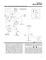
Page 25: ...and an air inlet valve At 20 water column the inlet vacuum switch will allow the Supervisor Controller to indicate that AIR FILTER MAINT is required The poppet type air inlet valve directly controls t...

Page 26: ...NOTES 20...

Page 27: ...your compressor s serial number Mixing of other fluids within the compressor will void all warranties Fluid should be changed every 1200 1400 hours or once a year whichever comes first The fluid shou...

Page 28: ...sed plant piping I LLL 4 46 fluid should not be used with PVC piping systems It may affect the bond at cemented joints Certain other plastic materials may also be affect ed I Plastic Pipe Institute Re...

Page 29: ...Section 3 SPECIFICATIONS 23 Figure 3 2 Identification LS20T 250 300 525 Water cooled with Supervisor Controller 02250139 799R00...

Page 30: ...NOTES 24...

Page 31: ...for space heating providing excessive pressure drop is not created across the fan Consult a Sullair office for assistance in utilizing this heat DO NOT install a water cooled or an air cooled aftercoo...

Page 32: ...After the electrical installation has been done it is necessary to check the direction of motor rotation With the control system in MANUAL MODE pull out the EMERGENCY STOP button and press once quickl...

Page 33: ...Section 5 SUPERVISOR CONTROLLER 27 Figure 5 1 Supervisor Controller Panel For information concerning all aspects of the Supervisor Controller consult the Supervisor Controller manual no 02250133 517...

Page 34: ...NOTES 28...

Page 35: ...and allows flow of fluid to the unit on startup Cuts off the reverse flow of air fluid mixture through compres sor discharge system at compressor shutdown Regulates flow of fluid to and around the coo...

Page 36: ...refer to Section 4 7 4 Start the compressor in the desired operating mode or 5 Slowly open the shut off valve to the service line 6 Check for possible leaks in piping 7 Slowly close the shut off valv...

Page 37: ...fluid filter element 3 Clean the return line strainers and orifices 4 Clean or replace the control line filter element 7 5 FLUID CHANGE Standard models are filled with LLL 4 46 fluid LLL 4 46 fluid s...

Page 38: ...e air filter maintenance mes sage is displayed The air filter is equipped with a primary and a secondary element As previously stated the Supervisor Controller will alert you as to when the primary el...

Page 39: ...s indicated by the Supervisor use the following procedure for separator replace ment 1 Remove the air receiver separator tank lid by removing the sixteen 16 hex head capscrews To assist with the remov...

Page 40: ...NCE Refer to Figure 7 4 The oil return sight glass sub assembly is attached to the separator tank Oil return sight glass maintenance should be per formed on a routine basis parallel to that of the flu...

Page 41: ...ng The reference pressure regulator should be set to maintain a 60 psig 4 14 bar downstream pressure to the inlet poppet valve The unload pressure reg ulator should be set at 170 psig 11 7 bar to cont...

Page 42: ...NOTES 36...

Page 43: ...hed Repair or replace as necessary kit available Readjust MAX P1 setpoint appropriately Cooling water temperature too high increase water flow water cooled Cooling water flow insufficient check water...

Page 44: ...and or dP2 on controller indicates high dP Thermal valve not functioning properly replace element Cooling air flow restricted clean cooler and check for proper ventilation air cooled Ambient temperatu...

Page 45: ...wdown Valve Defective Blowdown Solenoid Valve Plugged or Frozen Control Lines Defective Discharge Check Valve Defective Oil Stop Valve Defective Pressure Relief Valve Check all pipes connections and c...

Page 46: ...NOTES 40...

Page 47: ...placement coil for solenoid valve 02250125 657 02250125 861 1 Repair kit for solenoid valve 02250125 653 I 02250125 843 1 Replacement coil for solenoid valve 02250125 653 02250125 855 1 Repair kit for...

Page 48: ...coupling element 250 300hp 186 224kw I II 02250075 399 1 Replacement drive coupling element 350hp 261kw I II 250006 267 1 LLL 4 46 fluid 5 gal can 249775 001 25 gal I Recommended spare parts II Due to...

Page 49: ...NOTES 43...

Page 50: ...Section 9 ILLUSTRATIONS AND PARTS LIST 44 02250137 909R00 9 3 MOTOR FRAME COMPRESSOR AND PARTS...

Page 51: ...1 2 837508 125 12 17 washer spr lock reg pltd 7 16 837807 112 24 18 washer spr lock reg pltd 3 4 837812 188 12 19 washer pl b reg pltd 3 4 838212 112 4 I Due to customized motor variances consult fact...

Page 52: ...Section 9 ILLUSTRATIONS AND PARTS LIST 46 02250137 907R03 9 4 AIR INLET SYSTEM...

Page 53: ...nipple pipe xs galv 3 8 x cl 823206 000 2 19 nut hex pltd 1 2 13 825208 448 1 20 nut hex f pltd 3 8 16 825306 347 4 21 capscr hex gr5 1 2 13 x 1 1 4 829108 125 2 22 capscr hex gr5 1 2 13 x 1 3 4 8291...

Page 54: ...Section 9 ILLUSTRATIONS AND PARTS LIST 48 02250137 907R03 9 4 AIR INLET SYSTEM...

Page 55: ...pipe 90m 1 4 x 1 4 ss 872204 025 1 30 plug str thd hol hx 1 5 16 12 875716 131 2 31 tee pipe 300 1 4 ss 876730 010 2 32 connector tube m 1 4 x 1 4 ss 876804 025 2 33 connector tube m 1 2 x 1 2 ss 876...

Page 56: ...Section 9 ILLUSTRATIONS AND PARTS LIST 50 02250138 702R00 9 5 AIR INLET SUB ASSEMBLY...

Page 57: ...14 060 1 9 spring com 144 inter 250042 384 1 10 o ring viton 1 x 1 8 826502 214 1 11 o ring viton 3 3 8 x 3 16 826502 340 1 12 capscrew ferry head hd 3 8 16 x 1 3 4 828406 175 18 13 capscr hex gr5 1 4...

Page 58: ...Section 9 ILLUSTRATIONS AND PARTS LIST 52 02250137 908R00 9 6 WATER COOLING SYSTEM...

Page 59: ...08 448 4 4 capscr hex gr5 1 2 13 x 1 1 4 829108 125 4 5 capscr hex gr5 1 2 13 x 1 1 2 829108 150 4 6 washer spr lock reg pltd 1 2 837808 125 8 7 washer pl b reg pltd 1 2 838208 112 12 8 plug pipe 1 2...

Page 60: ...Section 9 ILLUSTRATIONS AND PARTS LIST 54 02250137 910R01 9 7 AIR PIPING SYTEM...

Page 61: ...4 807400 030 1 12 elbow pipe 90 deg 3000 2 1 2 807400 100 1 13 connector tube m 3 4 x 3 4 810212 075 1 14 connector tube m 2 x 2 810232 200 2 15 elbow tube 90 deg m 3 4 x 3 4 810512 075 1 16 elbow tub...

Page 62: ...Section 9 ILLUSTRATIONS AND PARTS LIST 56 02250137 912R01 9 8 FLUID PIPING SYSTEM...

Page 63: ...1 15 elbow tube str thrd 1 1 2 x 1 7 8 811624 188 4 16 connector tube str thd 1 1 2 x 1 7 8 811824 188 2 17 nut hex pltd 1 2 13 825208 448 4 18 nut hex f pltd 5 16 18 825305 283 4 19 o ring viton 2 1...

Page 64: ...Section 9 ILLUSTRATIONS AND PARTS LIST 58 02250139 798R00 9 9 WATER PIPING SYSTEM...

Page 65: ...x 1 1 2 810224 150 5 8 elbow tube 90 deg m 1 1 2 x 1 1 2 810524 150 1 9 nut hex pltd 1 2 13 825208 448 2 10 capscr hex gr5 1 2 13 x 1 1 4 829108 125 2 11 washer spr lock reg pltd 1 2 837808 125 2 12 e...

Page 66: ...Section 9 ILLUSTRATIONS AND PARTS LIST 60 02250137 911R01 9 10 DISCHARGE SYSTEM...

Page 67: ...t x 1 32 02250125 774 1 16 orifice plug brass 1 8 npt x 3 32 02250125 776 1 17 sightglass orf block sae 02250126 129 2 18 valve assy 3 x m85 III 02250127 507 1 19 nut hex m85 2 6h 02250130 997 1 20 pl...

Page 68: ...Section 9 ILLUSTRATIONS AND PARTS LIST 62 02250137 911R01 9 10 DISCHARGE SYSTEM...

Page 69: ...x 1 8 826502 236 1 43 capscr hex gr5 1 2 13 x 3 829108 300 2 44 capscr hex gr5 5 8 11 x 1 1 4 829110 125 8 45 capscr hex gr5 5 8 11 x 1 3 4 829110 175 4 46 capscr hex gr5 3 4 10 x 2 829112 200 1 47 c...

Page 70: ...Section 9 ILLUSTRATIONS AND PARTS LIST 64 02250137 911R01 9 10 DISCHARGE SYSTEM...

Page 71: ...mber description number quantity 60 elbow tube 90 deg m 1 4 x 1 4 ss 877004 025 1 61 elbow tube 90 deg m 1 2 x 1 2 ss 877008 050 1 62 elbow female str thd 1 1 16 878312 106 1 63 tee pipe 1 2 2000 ss 8...

Page 72: ...Section 9 ILLUSTRATIONS AND PARTS LIST 66 02250137 914R02 9 11 CONTROL START SYSTEM...

Page 73: ...t IV 02250139 080 2 17 support bracket vlv assy ls20t 575 02250139 081 1 18 support bracket vlv assy ls20t 575 02250139 082 1 19 nipple conduit 1 2 x 1 5 250007 169 3 20 grip cord so 12 4 st 1 2 25001...

Page 74: ...Section 9 ILLUSTRATIONS AND PARTS LIST 68 02250137 914R02 9 11 CONTROL START SYSTEM...

Page 75: ...spr lock reg pltd 1 2 837808 125 4 37 washer pl b reg pltd 3 8 838206 071 4 38 washer pl b reg pltd 1 2 838208 112 4 39 bulkhead pipe 1 4 npt 841500 004 4 40 locknut conduit 1 2 847200 050 6 41 bushin...

Page 76: ...Section 9 ILLUSTRATIONS AND PARTS LIST 70 9 12 CONTROL PANEL 02250138 633R00...

Page 77: ...control Supervisor III display mod 02250119 330 1 7 decal Supervisor front 02250130 344 1 8 panel instrument Supervisor 02250134 463 1 9 block contact 1nc 250027 125 1 10 switch per red push pull e22...

Page 78: ...Section 9 ILLUSTRATIONS AND PARTS LIST 72 9 13 ENCLOSURE 02250138 672R00...

Page 79: ...l roof w vent fan cut out 250022 724 1 16 channel btm sill ts20 ls25s encl 250022 772 2 17 panel fiberglass 23 5 x 23 5 x 2 250023 576 2 18 channel btm sill 250028 543 2 19 panel roof encl 20 16 25002...

Page 80: ...Section 9 ILLUSTRATIONS AND PARTS LIST 74 9 13 ENCLOSURE 02250138 672R00...

Page 81: ...75 8 35 screw hex ser washer 5 16 18 x 3 4 829705 075 78 36 screw hex ser washer 5 16 18 x 1 829705 100 14 37 washer spr lock reg pltd 3 8 837806 094 4 38 washer pl b reg pltd 5 16 838205 071 2 39 eye...

Page 82: ...Section 9 ILLUSTRATIONS AND PARTS LIST 76 9 14 DECAL GROUP...

Page 83: ...rning food grade lube 250003 144 1 3 sign warning ground fault 049852 1 4 decal warning auto start 250017 903 1 5 sign danger electrocution 049850 1 6 sign warning hot surfaces 407408 3 7 sign warning...

Page 84: ...Section 9 ILLUSTRATIONS AND PARTS LIST 78 9 14 DECAL GROUP...

Page 85: ...danger high voltage 042218 1 12 decal rotation 250021 564 1 13 decal rotation 250021 286 1 14 decal fluid LLL 4 46 02250145 602 1 15 decal water inlet outlet 049873 1 16 decal water in 250019 107 1 1...

Page 86: ...Section 9 ILLUSTRATIONS AND PARTS LIST 80 9 14 DECAL GROUP...

Page 87: ...decal ISO 9001 02250057 624 1 23 decal protective earth ground 02250075 045 1 24 decal earth ground 02250075 046 1 25 decal PE designation 02250075 540 1 26 decal electrical component ID 250038 457 1...

Page 88: ...Section 9 ILLUSTRATIONS AND PARTS LIST 82 9 15 DECAL LOCATION OPEN MODEL...

Page 89: ...7 decal warning auto start 250017 903 1 8 decal autostart 041065 1 9 sign warning sever fan 049855 2 10 decal LS20T black 4 ht 02250071 287 1 11 decal water drain 250022 810 1 12 decal ISO 9001 02250...

Page 90: ...Section 9 ILLUSTRATIONS AND PARTS LIST 84 9 16 DECAL LOCATION ENCLOSED MODEL...

Page 91: ...ting 241814 4 6 decal Sullair logo 4 x 32 black 02250059 060 1 7 sign warning sever fan port 049965 2 8 sign warning compressor fluid fill cap 049685 1 9 decal rotation 250021 564 1 10 decal water in...

Page 92: ...Section 9 ILLUSTRATIONS AND PARTS LIST 86 9 17 DECAL LOCATION CONTROL BOX...

Page 93: ...cal danger high voltage 042218 1 3 decal V 460 3 60 international I 02250069 399 1 4 decal earth ground 02250075 046 1 I Due to custom voltage requests voltage decal may vary For positive identificati...

Page 94: ...Section 9 ILLUSTRATIONS AND PARTS LIST 88 9 18 WIRING DIAGRAM LS20T 525 PSIG 02250137 917R01...

Page 95: ...NOTES 89...

Page 96: ...com SULLAIR CORPORATION 3700 East Michigan Boulevard Michigan City Indiana 46360 U S A www sullair com Telephone 1 800 SULLAIR U S A Only or 1 219 879 5451 Fax 219 874 1273 PARTS DEPARTMENT Fax 219 87...

Reviews: