Sub-Zero 700BC, Install Manual
The Sub-Zero 700BC Energy Manual is a comprehensive user manual for this state-of-the-art refrigerator, providing detailed instructions and information for optimal energy efficiency and usage. Easily download this manual for free from our website and unlock the full potential of your appliance.
Share
Download


Reviews:
No comments
Related manuals for 700BC
JR-N40B
Brand: Haier Pages: 8
JQ-F110C
Brand: Haier Pages: 8
JQ-F160B
Brand: Haier Pages: 8
JF-ND110A
Brand: Haier Pages: 16
JF-NC429A
Brand: Haier Pages: 8
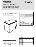
HSHF-20C
Brand: Haier Pages: 8
LW-194B
Brand: Haier Pages: 16

Profile PSB42YGXSV
Brand: GE Pages: 1

ICF198W
Brand: Inalto Pages: 14

BF051AF
Brand: VALERA Pages: 2

TropiCool TC07DC
Brand: Waeco Pages: 144

JLCH100
Brand: John Lewis Pages: 12

CG1442E
Brand: SUNFEEL Pages: 64

WVE16402 W
Brand: Whirlpool Pages: 1

WVE1862
Brand: Whirlpool Pages: 2

WV1600 NFW
Brand: Whirlpool Pages: 9

WHM 3111
Brand: Whirlpool Pages: 8

WHH07DC6
Brand: Whirlpool Pages: 8


