background image


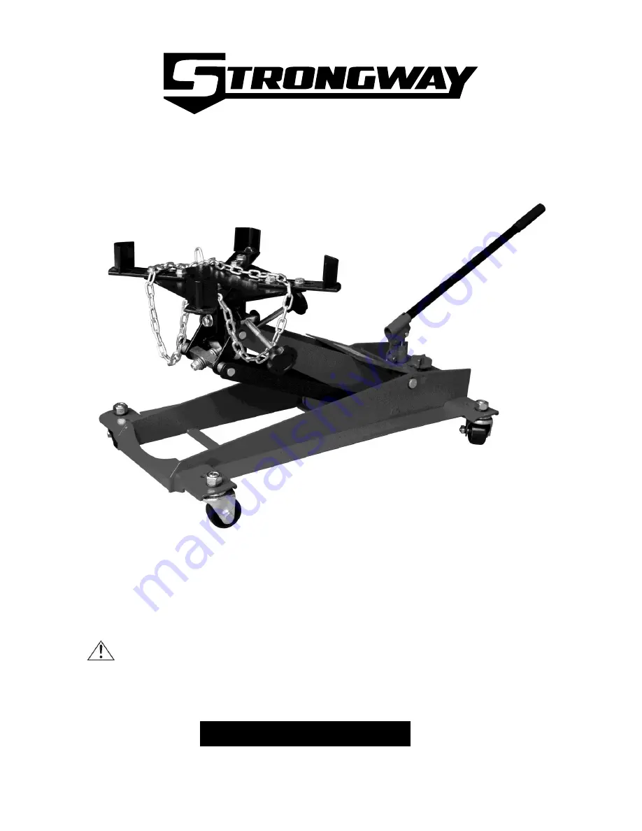
1000-LB.LOW PROFILE TRANSMISSION JACK 

OWNER’S MANUAL 


WARNING:


Read carefully and understand all 

ASSEMBLY AND OPERATION INSTRUCTIONS


before operating. Failure to follow the safety rules and other basic safety precautions 
may result in serious personal injury. 


Item# 46193 

Summary of Contents for 46193

Page 1: ... JACK OWNER S MANUAL WARNING Read carefully and understand all ASSEMBLY AND OPERATION INSTRUCTIONS before operating Failure to follow the safety rules and other basic safety precautions may result in serious personal injury Item 46193 ...

Page 2: ...rsal mounting head provides a wide fore and aft tilt range Manual operated hydraulic system that includes a bypass system to prevent over extension and accidental overloading Low profile design and four heavy duty steel swivel casters provide easy maneuvering throughout the shop Fits most transmissions This product is tested for reliability and safety to meet ASME PALD Standards TECHNICAL SPECIFIC...

Page 3: ...it in a secure place out of the reach of children Inspect it for good working condition prior to storage and before re use Not for use by children or people with reduced mental capacity Do not use under the influence of drugs or alcohol Ensure children and other bystanders are kept at a safe distance when using jack INSPECTION Inspect the jack carefully before each use Ensure the jack is not damag...

Page 4: ...s of this manual Failure to operate this equipment as directed may cause injury or death The distributor is not responsible for any damages or injury caused by improper use or neglect Always use Jack Stands DO NOT USE wood blocks or any other non approved load sustaining devices The manufacturer only warrants loads to be sustained by jack stands that meet current ASME standards DO NOT USE wood blo...

Page 5: ...is not level can cause loss of load or damage to the jack Do not raise or lower the vehicle unless tools materials and people are clear When the lift is being lowered make sure everyone is standing at least six feet away Be sure there are no tools or equipment left under or around the jack before lowering Always lower the jack slowly WARNING DO NOT USE THE JACK TO SUPPORT OR STABILIZE A LOAD Using...

Page 6: ... these instructions Do not modify the jack in any way Unauthorized modification may impair the function and or safety and could affect the life of the equipment There are specific applications for which the jack was designed Always check for damaged or worn out parts before using the jack Broken parts will affect the equipment operation Replace or repair damaged or worn parts immediately When jack...

Page 7: ...ddle and attach with washer 74 and hex nut 73 3 Screw the pump handle 1 into the socket 2 4 Tighten knob 26 clockwise to close the pump release valve Pump handle up and down to lift the whole stroke Release knob 26 for lowering Test jack raising and lowering operation several times before use ...

Page 8: ...rom the parts breakdown Perform the following Air Purge Procedure to remove any air that may have been introduced into the hydraulic system as a result of product shipment and handing This step is to be completed without any weight on the jack 1 Carefully and slowly pinch oil fill plug 30 to release trapped air ...

Page 9: ...instructions for system purge procedure 3 Inspect before each use Do not use if bent broken or cracked components are noted OPERATION All numbers in parenthesis refer to the index number from the parts breakdown 1 Move the jack into position 2 Turn the knob 26 clockwise fully to close the valve 3 Move the pump lever 1 up and down to raise the saddle 4 Adjust the angle screws 59 66 to align with th...

Page 10: ...ddle 6 Remove the transmission from the vehicle 7 Turn the knob 26 counter clockwise slowly to lower the saddle Always lower the saddle slowly Always transport the load in the lowered position with the chains securely fastened 8 Reverse this procedure when mounting the transmission ...

Page 11: ... are not self lubricating inspect the equipment before use and lubricate when necessary After cleaning lubricate the equipment using light penetrating oil lubricating spray Use a good lubricant on all moving parts For light duty use lubrication once a month For heavy and constant use lubrication recommended every week NEVER USE SANDPAPER OR ABRASIVE MATERIAL ON THESE SURFACES Rust Prevention Check...

Page 12: ...evel and to fill remove oil filler plug 30 1 Position the jack on level ground and lower the saddle 2 Remove the oil plug 3 Fill the oil case until oil level to 80 full 4 Replace oil plug 5 Perform the Air Purge Procedure TO REPLACE JACK OIL 1 Position the jack on level ground and lower the saddle 2 Open release valve by turning handle counter clockwise 4 full turns ...

Page 13: ...13 3 Remove the oil fill plug 4 Turn the jack on its side so that old oil will drain from the oil fill hole 5 Position the jack on level ground and lower the saddle ...

Page 14: ...RADE HYDRAULIC JACK OIL DO NOT USE HYDRAULIC BRAKE FLUID ALCOHOL GLYCERINE DETERGENT MOTOR OIL OR DIRTY OIL USE OF A NON RECOMMENDED FLUID CANCAUSE DAMAGE TO A JACK AVOID MIXING DIFFERENT TYPES OF FLUID AND NEVER USE BRAKE FLUID TURBINE OIL TRANSMISSION FLUID MOTOR OIL OR GLYCERIN IMPROPER FLUID CAN CAUSE PREMATURE FAILURE OF THE JACK AND THE POTENTIAL FOR SUDDEN AND IMMEDIATE LOSS OF LOAD DISPOSE...

Page 15: ... when necessary 2 A coating of light lubricating oil to pivot points Axles and hinges will help to prevent rust and assure that wheels casters and pump assemblies move freely 3 Periodically check the pump piston 32 and ram 7 for signs of rust or corrosion Clean as needed and wipe with an oil cloth ...

Page 16: ...NG WILL NOT LIFT TO FULL EXTENSION CAUSES AND SOLUTIONS Release valve is not completely closed Turn handle clockwise Weight Capacity Exceeded Air is in the hydraulics Purge air from system Low oil level Add oil as required Oil reservoir is overfilled Drain excessive oil Lubricate moving parts Jack is binding or foreign obstruction Power unit malfunctioning Replace the power unit ...

Page 17: ...17 ASSEMBLY DIAGRAM ...

Page 18: ...0 1 14 Ball 3 GB308 1 15 Spring Seat TQ22001 1 24 1 16 Spring QLQD2A 2 18 1 17 Adjust Pressure Screw T91004 38 1 18 O Ring 5 8x2 8 QLQ2 1 14 1 19 Safety valve cap T91004 39 1 20 Ball 6 GB308 2 21 Spring T91207F 54 1 22 Ball 9 GB308 1 23 Spring TE05001 3 17 1 24 Washer TQ22001 1 18 1 25 Screw M12X20 GB70 1 26 Release Valve Rod QF4 2A 1 27 O Ring 7 7X1 9 QLQ2 1 17 1 28 Base TE05001 3 08 1 29 Conical...

Page 19: ...4 2 1 55 Rotation Shaft Of Flat Roof TE05001 4 14 1 56 Washer 12 GB97 1 1 57 Nut M12X1 5 GB6173 1 58 Hand Wheel TE05001 4 4 2 59 Front And Back Screw TE05001 4 5 1 60 Rod Link Of Flat Roof TE05001 4 6 2 61 Shaft Cover TE05001 4 8 2 62 Front Rod Link Of Flat Roof TE05001 4 10 1 63 Plane bearing 8200 GB301 3 64 Washer 10 GB97 1 12 65 Nut M10 GB889 2 66 Left And Right Screw TE05001 4 7 1 67 Small Sha...

Page 20: ...ent illustrations provided are a convenient reference of location and position in the assembly sequence When ordering parts the following will be required Model Number Serial Number and Description The distributor reserves the rights to make design changes and or improvements to product lines and manuals without notice For replacement parts and technical questions please call 1 800 222 5381 ...

Page 21: ... by make and model number and follow the claim instructions that will be provided The product and the purchase receipt must be provided to Us in order to process Your warranty claim Any returned product that is replaced or refunded by Us becomes our property You will be responsible for return shipping costs or costs related to Your return visit to a retail store Remedy Limits Product replacement o...

Reviews: