StewMac MXR PHASE 90, Instructions Manual
The StewMac MXR PHASE 90 pedal is a versatile and timeless classic for your guitar rig. Unlocking a mesmerizing array of swirling phase tones, this compact powerhouse is a must-have. To help you unleash its full potential, a comprehensive and easy-to-follow Instructions Manual is available for free download at our website.
Share
Download


Reviews:
No comments
Related manuals for MXR PHASE 90

HALO
Brand: Keeley Pages: 12

PPM1008
Brand: Mackie Pages: 32

JBL CSM-21
Brand: Harman Pages: 56

Vantage Pro2 6312 Console
Brand: DAVIS Pages: 56

RotoChoir
Brand: Tech 21 Pages: 4

Pedal I/O 7U Case Adapter
Brand: Intellijel Pages: 13

SCM262E
Brand: Shure Pages: 10

MDR 1064
Brand: Samson Pages: 2

AMX7323
Brand: Audio2000's Pages: 6

X-77
Brand: Fostex Pages: 43
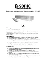
PE-6830
Brand: Q-Sonic Pages: 9

Groovebox MC-707
Brand: Roland Pages: 121

Starlight Echo Station
Brand: Universal Audio Pages: 3

F-Audio ECHOBANDIT
Brand: Nembrini Audio Pages: 8

7510B
Brand: JBL Pages: 28

PMX-420
Brand: Nady Audio Pages: 12

SWISS ARMY SM 26B
Brand: Rane Pages: 8

RM6
Brand: Rane Pages: 24


