background image

Model ST1007/ST1012/ST1014

***IMPORTANT UPDATE***

Applies to Models Mfd. Since 09/17

and Owner's Manual Printed 04/16 

Phone: (800) 840-8420 • Tech Support: [email protected] • Web: www.woodstockint.com

The following change was recently made to these machines since the owner's manuals were printed:

• 

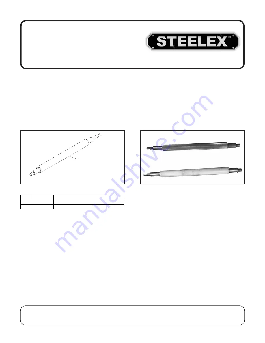
Changed outfeed roller from serrated steel to rubber.

Aside from the information contained in this update, all other content in the owner's manual applies and MUST be 

read and understood for your own safety. IMPORTANT: Keep this update with the owner's manual for future 

reference

If you have any further questions, contact our Technical Support.

COPYRIGHT © AUGUST, 2017 BY WOODSTOCK INTERNATIONAL, INC.

WARNING: NO PORTION OF THIS MANUAL MAY BE REPRODUCED IN ANY SHAPE OR FORM WITHOUT

THE WRITTEN APPROVAL OF WOODSTOCK INTERNATIONAL, INC.

Printed in China

READ THIS FIRST

#19144BL

163V2 
(ST1007, ST1012)

68V2
(ST1014)

V2 Outfeed Roller

REF PART #

DESCRIPTION

163V2 XST1007163V2 OUTFEED ROLLER (RUBBER) V2.09.17 (ST1007)
163V2 XST1012163V2 OUTFEED ROLLER (RUBBER) V2.09.17 (ST1012)
68V2 XST1014068V2 OUTFEED ROLLER (RUBBER) V2.09.17 (ST1014)

V1 & V2 Outfeed Roller Photos

V2

V1

Summary of Contents for ST1007

Page 1: ...nderstood for your own safety IMPORTANT Keep this update with the owner s manual for future reference If you have any further questions contact our Technical Support COPYRIGHT AUGUST 2017 BY WOODSTOCK...

Page 2: ...echnical Support techsupport woodstockint com COPYRIGHT APRIL 2016 BY WOODSTOCK INTERNATIONAL INC WARNING NO PORTION OF THIS MANUAL MAY BE REPRODUCED IN ANY SHAPE OR FORM WITHOUT THE WRITTEN APPROVAL...

Page 3: ...h defects or other reproductive harm Some examples of these chemicals are Lead from lead based paints Crystalline silica from bricks cement and other masonry products Arsenic and chromium from chemica...

Page 4: ...t Tools 36 Optional Adjustment Tools 36 Lubrication 37 Tensioning Replacing V Belts 38 Anti Kickback Pawls 39 SERVICE 40 Troubleshooting 40 Adjusting Feed Rollers Chip Breaker Pressure Bar 42 Adjustin...

Page 5: ...ct glass metal liquids asbestos silica animal parts biohazards burning material ashes etc 5 Always disconnect power before servicing or cleaning 6 Do not expose to rain or wet areas 7 Keep hands long...

Page 6: ...hase 60 Hz Full Load Current Rating 15A 19A Minimum Circuit Size 20A 30A Connection Type Cord Plug Power Cord Included Yes Power Cord Length 6 ft 6 1 2 ft Power Cord Gauge 12 AWG Plug Included Yes Inc...

Page 7: ...r of Knives 3 N A N A Knife Type HSS Single Sided Solid N A N A Knife Length 15 in N A N A Knife Width 1 in N A N A Knife Thickness 1 8 in N A N A Knife Adjustment Springs or Jack Screws N A N A Numbe...

Page 8: ...ify the external features of the planer A Control Panel B Table Height Handwheel C Feed Roller Gearbox D Table Lock Knob E Feed Rate Selector F Table Height Scale G Retractable Lifting Rods H Caster W...

Page 9: ...he manual and stay safe when operating this machine A Control Panel for Magnetic Switch Green START button turns motor ON when pressed Red Emergency STOP button turns motor OFF when pressed for safety...

Page 10: ...d Roller Pulls the workpiece toward the cutterhead C Chip Breaker Breaks off chips created by the cutterhead to prevent tear out and diverts the chips to the dust hood D Chip Deflector Directs chips i...

Page 11: ...Make workshop kid proof DANGEROUS ENVIRONMENTS Do not use machin ery in areas that are wet cluttered or have poor lighting Operating machinery in these areas greatly increases the risk of accidents an...

Page 12: ...act with moving parts or flying debris Make sure they are properly installed undamaged and working correctly BEFORE operating machine FORCING MACHINERY Do not force machine It will do the job safer an...

Page 13: ...ECURE KNIVES INSERTS Loose knives or improp erly set inserts can become dangerous projectiles or cause machine damage Always verify knives inserts are secure and properly adjusted before operation KIC...

Page 14: ...operly sized for safe operation Circuit Requirements This machine must be connected to the correct size and type of power supply circuit or fire or electrical damage may occur Read through this sectio...

Page 15: ...l if you do not understand these grounding requirements or if you are in doubt about whether the tool is properly grounded If you ever notice that a cord or plug is damaged or worn disconnect it from...

Page 16: ...e manu al to become familiar with the controls and opera tions before starting the machine UNPLUG power cord before you do any assembly or adjustment tasks Otherwise serious personal injury to you or...

Page 17: ...t Lifting Lever and Pin 1 E Handwheel and Handle 1 F Extension Wings 2 Tools Figure 8 G Hex Wrenches 2 5 3 4 6mm 1 Ea H Wrenches 8 10 14 17 17 19mm 1 Ea Hardware See Hardware Recognition Chart I Knife...

Page 18: ...2 13 4 11 2 11 4 1 LINES ARE 1MM APART 5mm 10mm 20mm 15mm 25mm 40mm 30mm 35mm 45mm 50mm 60mm 55mm 70mm 65mm 75mm W A S H ER DIAM E T E R 5 8 W A S H ER DIAM E T E R 9 16 1 2 W A S H ER DIA M E T E R W...

Page 19: ...ing Disposable rags Cleaner degreaser WD 40 works well Safety glasses disposable gloves Plastic paint scraper optional Basic steps for removing rust preventative 1 Put on safety glasses 2 Coat the rus...

Page 20: ...ual See below for required space allocation Physical Environment The physical environment where the machine is operated is important for safe operation and longev ity of machine components For best re...

Page 21: ...machine off pallet see Figure 10 Tip When positioning lift forks place shop rags or cardboard between forks and cabinet stand to avoid scratching paint Figure 10 Lifting planer with forklift To lift...

Page 22: ...apped holes on the side of the table to the cast iron wings and lightly secure the wings in place with the 3 M8 1 25 x 30 hex bolts and the 8mm lock and flat washers for the ST1014 use 3 M8 1 25 x 35...

Page 23: ...4 dust hose ST1007 ST1012 or a 5 dust hose ST1014 over the dust port and secure in place with a hose clamp see Figure 17 Tug the hose to make sure it does not come off Note A tight fit is necessary fo...

Page 24: ...t and re adjust if required Note Forquickandeasytablerollersetup consid er purchasing a Rotacator This handy tool allows you to watch the height of the table rollers you adjust it giving you accuracy...

Page 25: ...rn machine ON Verify motor starts up and runs smoothly without any unusual problems or noises 6 Press STOP button to turn machine OFF 7 WITHOUT resetting STOP button try to start machine by pressing t...

Page 26: ...ne controls components discussed later in this manual are easier to understand Due to its generic nature this overview is NOT intended to be an instructional guide This machine will perform many types...

Page 27: ...idual components Excessive Warping Workpieces with excessive cupping bowing or twisting are dangerous to cut because they are unstable and often unpredictable when being cut DO NOT use workpieces with...

Page 28: ...true cupped or warped stock on a jointer before planing Below is a list of wood characteristics you may encounter when planing The following descriptions of defects will give you some possible answer...

Page 29: ...th of cut Rippled Cut Problem Regularly spaced indentations across face of workpiece are caused by excessive outfeed roller pressure or excessive feed rate Solution Reduce outfeed roller pressure redu...

Page 30: ...e 0 002 0 020 Figure 24 Recommended bed roller height above the table surface Bed rollers that are not adjusted to the correct height or out of alignment with each other can cause poor finishes incons...

Page 31: ...with knives can result in severe cuts Take great caution whenever work ing with or around cutterhead knives Wear heavy leather gloves to reduce risk of severe cuts To reduce risk of shock or accidenta...

Page 32: ...wedge type gibs and gib bolts lock the knives in place Choose whichever method meets your needs but understand that the screws and springs cannot be used together you must choose one and remove the o...

Page 33: ...lacing Cutterhead Inserts ST1012 ST1014 The helical cutterhead is equipped with indexable carbide inserts that can be rotated to reveal any one of their four cutting edges If one edge of the insert be...

Page 34: ...actual machine not shown Torx Screw Cutterhead Insert 4 Remove any sawdust or debris from head of insert Torx screw and surrounding area see Figure 32 6 Replace insert so that a fresh cutting edge fa...

Page 35: ...s Accurate to 0 001 Indicator rotates 360 Figure 33 Model W1218A Rotacator The W1834 20 Blade Grinder is ideal for sharpen ing planer and jointer knives High quality cast iron construction together wi...

Page 36: ...042 6 Digital Caliper lets you switch between decimal and fractional inches and millime ters Large digital readout makes precision measure ments easy with a resolution of 0 0005 Features include harde...

Page 37: ...is 0 01mm and maximum measuring speed is 1 5m s Features inches and millimeters conversion button plus and minus preset buttons and zero setting on button Each Digital Scale includes an extra long lif...

Page 38: ...d rollers Weekly Check Clean cutterhead Lubricate the four columns Change gear box oil should be performed after the first 20 hours when planer is new Monthly Check Inspect V belt tension damage or we...

Page 39: ...r superior adjustment Basic Adjustment Tools To make the setup process easier and more accurate many woodworkers purchase optional aftermarket products like the Rotacator and the Planer Pal Rotacator...

Page 40: ...inspection Use a general purpose grease to lubricate the chain Feed Rollers Lubricate feed rollers daily before start up Figure 48 shows the lubrication points for the feed rollers These are screws t...

Page 41: ...Always replace the V belts with a matched set of three or belt tension may not be even among the belts causing premature belt failure V belts and pulleys will be hot after operation Allow them to coo...

Page 42: ...ck pawls is essential to the safe operation of the planer If they aren t working properly they will not pro tect you if a kickback occurs 4 If V belts need to be replaced raise motor to release belt t...

Page 43: ...earings at fault 1 Reduce feed rate depth of cut 2 Only cut wood ensure moisture is below 20 3 Allow motor to cool reset overload if necessary and reduce depth of cut Contact Tech Support if relay fre...

Page 44: ...e a smaller depth of cut Reduce cutting depth when planing hard woods 3 Slow down feed rate 4 Adjust both sides of chipbreaker to correct height 5 Replace affected knife Page 28 or have it sharpened r...

Page 45: ...es and a feeler gauge set can be used but care must be taken when jointing the wood to achieve accurate results Distance Below Knife Insert at BDC Figure 53 A Infeed Roller 0 040 B Chip Breaker 0 040...

Page 46: ...nfeed roller 11 Re check both sides of infeed roller and if nec essary make further adjustments until infeed roller height from side to side is 0 040 below BDC of cutterhead knife insert then re tight...

Page 47: ...all adjustments For best results make the 2x4 square with a jointer and table saw before cutting it in half 2 Make sure knives are set to correct height refer to Adjusting Replacing Knives on Page 28...

Page 48: ...eaker 15 Repeat Steps 13 14 for pressure bar height adjustment but adjust the gap to 0 040 see Figure 61 Figure 62 Setting table roller height 12 Repeat Steps 10 11 with outfeed roller only adjust the...

Page 49: ...tent surface use less spring tension If you are planing rough lumber with inconsis tent surfaces use greater spring tension to keep the stock moving through the planer If the workpiece consistently st...

Page 50: ...nd of the cutterhead If the block of wood will not fit or if the block is below the cutterhead body measure this gap with a feeler gauge If the difference is more than 0 002 then the table needs to be...

Page 51: ...66 To adjust table more than 0 016 1 Remove the side cabinet plate 2 On the underside of the table there is a chain drive and five sprockets as shown in Figure 67 The four sprockets in the corners co...

Page 52: ...Figure 69 Loosen the screws and lift lower the table until the table and the cutterhead body are parallel with each other and the table is parallel with the head casting from front to back This may r...

Page 53: ...g pulley alignment 3 Re check pulleys and repeat Step 2 if necessary 4 Once pulleys are properly aligned re tighten all fasteners then replace belt cover and cabinet covers 2 Remove both cabinet cover...

Page 54: ...otor Thermal Relay Motor Contactor ST1007 ST1012 Electrical Components Control Box Power Lamp Start Button Stop Button Figure 73 ST1007 ST1012 control panel Figure 75 ST1007 ST1012 magnetic switch ass...

Page 55: ...citor 20MFD 450VAC Start Capacitor 200MFD 250VAC CONTROL PANEL from Behind A1 A2 98 2T1 6T3 97 4T2 2T1 6T3 4T2 1L1 5L3 13NO 14NO 3L2 96 95 NHD C 09D NHD NTH 21 17 18 20 2 1 O R MAGNETIC SWITCH ASSY Co...

Page 56: ...rt Capacitor 250MFD 250VAC CONTROL PANEL from Behind A1 A2 98 2T1 6T3 97 4T2 2T1 6T3 4T2 1L1 5L3 13NO 14NO 3L2 96 95 NHD C 09D NHD NTH 21 17 18 20 2 1 O R MAGNETIC SWITCH ASSY Contactor Thermal Overlo...

Page 57: ...15 20 Planers Mfd Since 3 16 ST1014 Electrical Components Figure 79 ST1014 magnetic switch assembly Figure 78 ST1014 control panel viewed from behind Start Power Stop Figure 77 Capacitors Figure 76 Mo...

Page 58: ...D C 35D NHD NTH 32 2 6 28 30 31 3 2 O R Contactor Thermal Overload Relay GROUND BLACK WHITE GREEN RED BLUE COLOR KEY Wt Wt Wt Wt Wt Gn Gn Gn Gn Gn Rd Rd Rd Rd Rd Rd Rd Rd Rd Rd Rd Rd Rd Rd Rd Rd Rd Bl...

Page 59: ...5 51 54 36 36 26 25 59 4 7 3 6 1 2 61 57 58 60 63 66 65 64 62 73 70 69 71 68 45 27 37 35 35 38 39 52 53 56 67 75 11 16 47 21 14 13 8 9 10 15 14 14 12 49 48 23 17 19 20 24 22 18 5 74 30 3 30 4 30 6 30...

Page 60: ...8 1 25 X 45 72 1 XST1007072 1 CONTACTOR NHD C 09D 230V 26 XST1007026 HEX NUT M8 1 25 72 2 XST1007072 2 OL RELAY NHD NTH 21 17 21A 27 XST1007027 FLAT WASHER 8MM 72 3 XST1007072 3 REAR MAG SW COVER 35 X...

Page 61: ...75 174 172 171 170 169 168 171 170 169 168 164 167 167 165 163 162 161 160 159 158 157 156 155 154 153 173 141 142 140 139 138 137 136 166 130 135 133 134 132 132 131 127 129 126 125 124 115 114 114 1...

Page 62: ...5 SET SCREW M6 1 X 18 125 XST1007125 FLANGE BOLT M6 1 X 12 176 XST1007176 HEX NUT M6 1 126 XST1007126 FOAM GASKET 177 XST1007177 STANDOFF HEX 127 XST1007127 GEAR BOX COVER 178 XST1007178 COLUMN LOCK R...

Page 63: ...EX BOLT M8 1 25 X 50 208 XST1007208 GEARED SHAFT 230 XST1007230 OIL DRAIN PLUG 209 XST1007209 BALL BEARING 6201 OPEN 231 XST1007231 FLANGE COVER 210 XST1007210 GEAR 232 XST1007232 CAP SCREW M5 8 X 12...

Page 64: ...1007319 SPROCKET 305 XST1007305 COLUMN 320 XST1007320 KEY 5 X 5 X 16 306 XST1007306 BALL BEARING 6302ZZ 321 XST1007321 FLAT WASHER 10MM 307 XST1007307 INT RETAINING RING 42MM 322 XST1007322 HEX NUT M1...

Page 65: ...X BOLT M8 1 25 X 30 413 XST1007413 ECCENTRIC SHAFT 405 XST1007405 FLAT WASHER 8MM 414 XST1007414 BALL BEARING 6203ZZ 406 XST1007406 LOCK WASHER 8MM 415 XST1007415 BED ROLLER 407 XST1007407 EXTENSION W...

Page 66: ...st be made of chemical resistant material COPYRIGHT WOODSTOCK INTERNATIONAL INC FOR SHOP FOX MACHINES ONLY DO NOT REPRODUCE OR CHANGE THIS ARTWORK WITHOUT WRITTEN APPROVAL Woodstock will not accept la...

Page 67: ...29 30 30 32 31 31 2 31 3 31 1 33 27 71 34 35 36 38 39 37 40 41 43 46 47 44 45 55 56 57 58 59 60 61 62 63 64 65 66 67 68 70 70 70 70 72 72 72 72 69 73 74 75 76 77 79 80 81 78 82 83 84 115 86 88 87 92 9...

Page 68: ...014075 SET SCREW M6 1 X 20 29 XST1014029 GEARBOX COVER PLATE L 76 XST1014076 HEX NUT M6 1 30 XST1014030 FLANGE BOLT M6 1 X 10 77 XST1014077 LOCKING ROD 31 XST1014031 CHAIN TENSIONER BRACKET ASSEMBLY 7...

Page 69: ...ND OFF 102 XST1014102 CUTTERHEAD PULLEY 109 XST1014109 FLAT WASHER 8MM 103 XST1014103 MOTOR PULLEY 110 XST1014110 HEX NUT M8 1 25 104 XST1014104 FLAT WASHER 8MM 111 XST1014111 COGGED V BELT MX 60 105...

Page 70: ...KEY 5 X 5 X 50 207 XST1014207 BALL KNOB M10 1 5 227 XST1014227 GASKET 208 XST1014208 GEARED SHAFT 228 XST1014228 GEARBOX 209 XST1014209 BALL BEARING 6201ZZ 229 XST1014229 CAP SCREW M8 1 25 X 50 210 XS...

Page 71: ...338 346 347 348 329 349 301 354 355 321 319 308 304 314 316 316 306 315 315 317 327 324 324 325 326 323 307 312 313 305 320 319 318 328 311 309 310 302 303 350 322 357 356 351 353 352 358 360 361 359...

Page 72: ...317 4 XST1014317 4 S CAPACITOR 300M 300V 351 XST1014351 BUTTON HD CAP SCR M5 8 X 20 317 5 XST1014317 5 MOTOR JUNCTION BOX 352 XST1014352 FLAT WASHER 5MM 317 6 XST1014317 6 MOTOR LABEL 353 XST1014353...

Page 73: ...401 XST1014401 MAIN TABLE 408 XST1014408 LOCKING ROD 402 XST1014402 BED ROLLER 409 XST1014409 STAR KNOB M12 1 75 403 XST1014403 BALL BEARING 6201ZZ 410 XST1014410 EXTENSION WING 404 XST1014404 ECCENT...

Page 74: ...22 XST1014522 HEX NUT M10 1 5 506 XST1014506 BALL BEARING 6202ZZ 523 XST1014523 CHAIN TENSION BRACKET 507 XST1014507 INT RETAINING RING 35MM 524 XST1014524 EXT RETAINING RING 15MM 508 XST1014508 DRIVE...

Page 75: ...G WARNING ACCIDENTAL INJURY HAZARD Disconnect power supply before adjustments setup or maintenance WARNING EYE EAR LUNG INJURY HAZARD Always wear safety glasses ear protection and respirator when usin...

Page 76: ...ST1007 12 14 15 20 Planers Mfd Since 3 16 73...

Page 77: ...that the defect resulted from causes not within the scope of Woodstock International Inc s warranty then the original owner must bear the cost of storing and returning the product This is Woodstock In...

Page 78: ...to a friend ______ Yes ______ No 6 What is your age group ______ 20 29 ______30 39 ______ 40 49 ______ 50 59 ______60 69 ______ 70 7 What is your annual household income ______ 20 000 29 000 ______ 3...

Page 79: ...TAPE ALONG EDGES PLEASE DO NOT STAPLE FOLD ALONG DOTTED LINE FOLD ALONG DOTTED LINE WOODSTOCK INTERNATIONAL INC P O BOX 2309 BELLINGHAM WA 98227 2309 Place Stamp Here...

Page 80: ......

Page 81: ......

Reviews: