


Installation and Service Instructions for
87,000; 87,100; 87,200; 87,400 and 87,600 Series
Important
Please read these instructions carefully before
installing, operating, or servicing your Stearns
brake. Failure to comply with these instructions
could cause injury to personnel and/or damage
to property if the brake is installed or operated
incorrectly. For definition of limited warranty/
liability, contact Rexnord Industries, LLC,
Stearns Division, 5150 International Dr.,
Cudahy, WI 53110, (414) 272-1100.
Caution
1. Installation and servicing must be made
in compliance with all local safety codes
including Occupational Safety and Health
Act (OSHA). All wiring and electrical
connections must comply with the National
Electric Code (NEC) and local electric
codes in effect.
2. Use of this brake in atmospheres
containing explosive gases and dusts
must be in accordance with NEC article
501. This brake is not suitable for use in
certain atmospheres containing explosive
gases and dusts.
HazLoc
inspection
authorities are responsible for verifying and
authorizing the use of suitably designed
and installed
HazLoc
equipment. When
questions arise consult local
Authority
Having Jurisdiction (AHJ)
.
3. To prevent an electrical hazard, disconnect
power source before working on the brake.
If power disconnect point is out of sight,
lock disconnect in the
off
position and tag
to prevent accidental application of power.
4. Make certain power source conforms to
the requirements specified on the brake
nameplate.
5. Be careful when touching the exterior of an
operating brake. Allow sufficient time for
brake to cool before disassembly. Surfaces
may be hot enough to be painful or cause
injury.
6. Do not operate brake with housing
removed. All moving parts should be
guarded.
7. Installation and servicing should be
performed only by qualified personnel
familiar with the construction and operation
of the brake.
8. For proper performance and operation,
only genuine Stearns parts should be used
for repairs and replacements.
9. After usage, the brake interior will contain
burnt and degraded friction material
dust. This dust must be removed before
servicing or adjusting the brake.
DO NOT BLOW OFF DUST using an air
hose. It is important to avoid dispersing
dust into the air or inhaling it, as this may
be dangerous to your health.
a. Wear a filtered mask or a respirator
while removing dust from the inside of
a brake.
b. Use a vacuum cleaner or a soft brush
to remove dust from the brake. When
brushing, avoid causing the dust to
become airborne. Collect the dust in a
container, such as a bag, which can be
sealed off.
10. Do not run motor with the brake in
the manual release position to avoid
overheating of friction disc.
11. Do not lubricate any parts of the brake.
12. Do not adjust brake torque. The nominal
static torque is factory pre-set and should
not be altered.
General Description
The 87,X00 Series is a spring-set, electrically
released disc brake for controlled stopping and
holding of a load. It is self-adjusting for friction
disc wear and mounts directly to a NEMA
C-face motor with 8-1/2” (AK) register and a
7-1/4” (AJ) bolt circle.
The 87,100 Series Brake mounts to a
10-1/2” AK diameter register and 9” (AJ) bolt
circle.
The brake is provided with a manual release
lever or rod. When the motor is off and the load
is to be moved without energizing the motor,
the manual release lever or rod should be
used. This removes the holding torque from the
motor shaft, allowing it to be rotated by hand,
however drag may be noted. The brake will
remain in the manual release position until the
release lever or rod is returned manually to its
set position, or until the brake is re-energized
electrically and the release lever or rod returns
to its set position automatically.
Note:
Fan-guard mounted brakes requiring
IP54 & IP55 protection may require additional
sealing measures beyond seals provided with
this brake. Pressurized sprays aimed at the
fan and brake hub surfaces can result in fluid
migration along the motor shaft and keyway,
and into the brake. The use of an appropriate
sealant such as
RTV
or a
forsheda
seal is
advised.
I. Installation Procedure - 87,000; 87,100;
87,400 and 87,600
A. Remove manual release knob (148) (on
pull type), housing nuts (15) and housing
(7). Housings equipped with side manual
release do not have release knob.
B. Depress solenoid plunger (29) and pull
release rod (146) back to lock brake
mechanism in manual release position or
wire tie plunger (29) to frame (79). The
87,600 Series Brake, brakes with optional
deadman manual release and brakes with
optional side manual release, the plunger
must be wire tied to the frame.
C. Remove entire support plate assembly
(142) by evenly unscrewing screw (142S).
Remove screws, conical spring washers,
and flat washers if supplied.
D. Remove pressure plate (5), friction disc (4),
and stationary disc (3).
Note 1
: Brakes with a single friction disc do
not have stationary discs. Vertically mounted
brakes will have special pins which hold spacer
springs and, in some cases, spring washers
except one-disc vertical below. Note color
coded sequence of springs and location of
washers, if used, or refer to Instruction Sheet
P/N 8-078-937-05 (Sheet 301.3) for proper
assembly of vertical mounting components.
E. Attach endplate (2) to NEMA C-face of
motor using four 1/2” diameter socket
head cap screws (not supplied) torque per
manufacturer’s specifications. (Head of
cap screws must not project above friction
surface.) If foot mounted, secure foot
mounting bracket to foundation. The use
of dowels to insure permanent alignment
is recommended. Foot, machine or C-face
mounted brakes must be carefully aligned
within .004” on concentricity and face
runout. Shaft runout should be within .002”
T.I.R. Maximum permissible shaft endfloat
is .020”.
Note 2
: If motor is to be ceiling mounted after
assembly, entire brake will have to be rotated
180° or “upside down” so it will be positioned
with solenoid plunger (29) above frame when
final assembly is mounted on ceiling. Similarly,
®
Spring-Set Disc Brakes
P/N 8-078-927-00
effective 07/14/2017
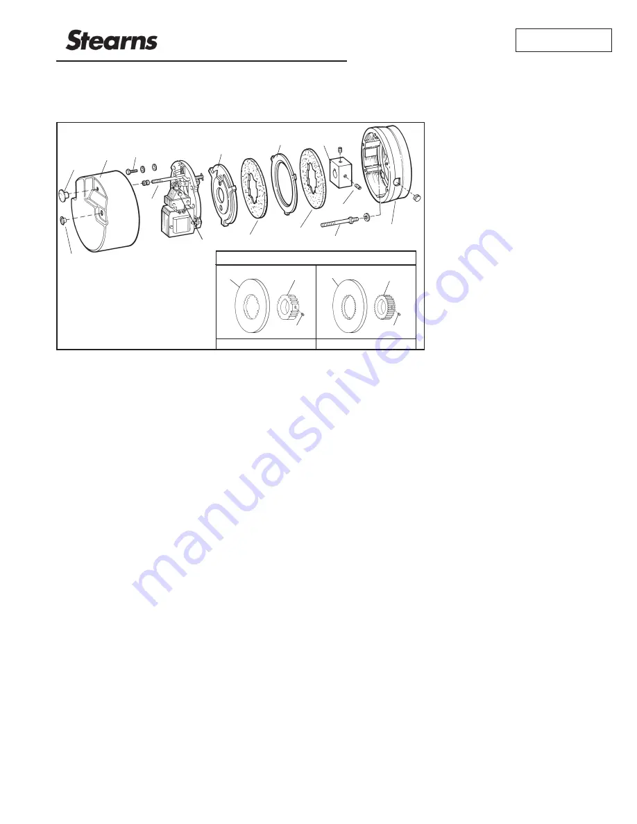
Figure 1
2
150
16S
16
3
4
4
29
5
146
142S
7
15
148
Splined Configuration
16S
16S
16B
16A
4B
4A
16 tooth
3.12 diameter
24 tooth
4.24 diameter


