Installation Manual
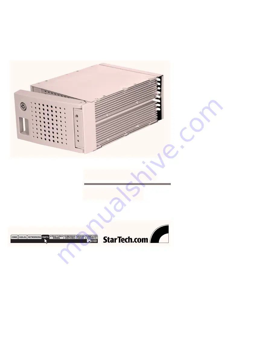
RAIDBAY3
Data Storage
3 Drive SCA U160 SCSI Lockable Backplane
Page 1: ...Installation Manual RAIDBAY3 Data Storage 3 Drive SCA U160 SCSI Lockable Backplane ...
Page 2: ...I drives into 2 5 25 inch drive bays full height 3 Cooling fans provide a combined 75 CFM of airflow Drives can be hot swapped if supported by the host RAID controller Several RAIDBAYs can be linked to form a larger array Lockable front door Activity LEDs for each drive Overheating alarm provides warning if the subsystem operating temperature exceeds 131F 55C Specifications Chassis rear SCSI conne...
Page 3: ...the button again to reset it to the original settings 2 Overheeating LED When overheating occurs the LED will be lit 3 HDD LEDs When you power on the system the three HDD LEDs will light up This idicates that the hard drives are properly installed Activity on the hard drive is indicated by a blinking LED 4 Power LED The LED is lit when the system is powered on 1 2 3 4 ...
Page 4: ...nel 1 Reset Switch for buzzer 2 External Reset Switch 3 SCSI Connector to Controller 4 SCSI ID Setting Switch 5 4 Pin Power 5V 12V 6 Buzzer 7 SCSI Connector for Terminator see Appendix for more details 1 2 3 4 5 6 7 ...
Page 5: ...On Off Off Off Off On Off Off On On Off Off Off Off On Off On Off On Off Off On On Off On On On Off ID2 ID4 ID8 SCSI ID 8 9 10 11 12 13 14 15 ID1 Off Off Off On On Off Off On Off On Off On On On Off On Off Off On On On On Off On Off On On On On On On On ID2 ID4 ID8 ...
Page 6: ...ws provided secure the hard drive to the tray 4 Slowly slide the tray back into the slot 5 When the tray is all the way back into the slot press the arm back in until you hear a click sound This indicates that the tray and hard drive are properly installed 6 Repeat these steps for the other two trays 7 Connect the flat cable from the upper connector to the controller or RAID card 8 Place the Termi...
Page 7: ...SI ID selector setting switches for HDD1 HDD2 and HDD3 See SCSI ID Number section for setting SCSI ID numbers 5 SW4 Pin definition Reset Switch button Note The function of SW4 is the same as that of the Reset button on the front panel When overheating occurs and the buzzer is sounding and the temperature LED is red press the Reset Switch from either the front panel or SW4 to stop the alarm When yo...