Starrett MVR200, User Manual
The Starrett MVR200 User Manual is a comprehensive guide for operating and maintaining your MVR200 device. Download this essential manual for free at manualshive.com, ensuring you have all the necessary information to optimize your experience with the product. Get started today with easy access to this invaluable resource.
Share
Download


Reviews:
No comments
Related manuals for MVR200

VE200G1A
Brand: Banner Pages: 11

HD3000
Brand: Janome Pages: 28

457A105
Brand: Singer Pages: 29

LS2-H550
Brand: Unicorn Pages: 43

MC S6 B
Brand: Racing Pages: 22

831U
Brand: Singer Pages: 46

281LY-B
Brand: Nakajima Pages: 22

3822-1/32
Brand: Pfaff Pages: 130

HCS2-1201
Brand: Happy Pages: 15

LS2-190
Brand: Mitsubishi Pages: 32

HT2008
Brand: Janome Pages: 86

Easy Step Plus MS 80
Brand: Impex Pages: 9
NL4-LBM Series
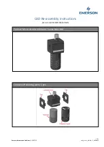
Brand: Emerson Pages: 3
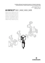
AVENTICS AS1
Brand: Emerson Pages: 47

MK740DSA
Brand: Merrylock Pages: 36

CP-170
Brand: JUKI Pages: 34

HZL-27Z
Brand: JUKI Pages: 24

HZL - 353Z Series
Brand: JUKI Pages: 35


