background image

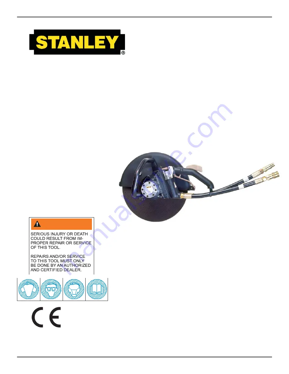
CO25

HYDRAULIC

CUT-OFF SAW

S

AFETY

, O

PERATION


AND

 M

AINTENANCE

 SERVICE MANUAL

Copyright

©

 The Stanley Works 2005

OPS/SVCE USA
Printed in U.S.A.
34956   8/2005 ver 2

Stanley Hydraulic Tools

3810 SE Naef Road

Milwaukie OR 97267-5698

503-659-5660

FAX 503-652-1780

www.stanley-hydraulic-tools.com

WARNING

Summary of Contents for CO25

Page 1: ...ND MAINTENANCE SERVICE MANUAL Copyright The Stanley Works 2005 OPS SVCE USA Printed in U S A 34956 8 2005 ver 2 Stanley Hydraulic Tools 3810 SE Naef Road Milwaukie OR 97267 5698 503 659 5660 FAX 503 652 1780 www stanley hydraulic tools com WARNING ...

Page 2: ...w This manual contains safety operation and routine maintenance instructions Servicing of hydraulic tools other than routine maintenance must be per formed by an authorized and certified dealer Please read the following warning SERIOUS INJURY OR DEATH COULD RESULT FROM THE IM PROPER REPAIR OR SERVICE OF THIS TOOL REPAIRS AND OR SERVICE TO THIS TOOL MUST ONLY BE DONE BY AN AUTHORIZED AND CERTIFIED D...

Page 3: ...OSES 11 TOOL OPERATION 11 STARTUP 11 GENERAL OPERATION 12 WET CUTTING 12 BROKEN CUT OFF WHEELS 12 SHUTDOWN 12 PERIODIC MAINTENANCE 13 THRUST COLLAR AND INSIDE OUTSIDE COLLAR INSPECTION 13 DRIVE SHAFT SPEED CHECK 13 BEARING CHECK 13 CARE AND STORAGE 13 CUTOFF WHEELS 13 TOOL 13 CUTOFF WHEEL REPLACEMENT 14 COLD WEATHER OPERATION 14 EQUIPMENT PROTECTION CARE 15 TROUBLESHOOTING 16 SPECIFICATIONS 17 ACC...

Page 4: ...All 5 Year of manufacture Baujahr année de fabrication Año de fabricacion Anno di fabbricazione 1998 Has been manufactured in conformity with EEC Type examination as shown Wurde hergestellt in Übereinstimmung mit EEC Typ Prüfung nach Est fabriqué conformément au x type s examiné s comme indiqué dans le tableau ci après Ha sido fabricado de acuerdo con tipo examen EEC como dice E stata costruita in...

Page 5: ...nel CAUTION WARNING DANGER NOTICE This is the safety alert symbol It is used to alert you to potential personal injury hazards Obey all safety messages that follow this symbol to avoid possible injury or death This safety alert and signal word indicate a potentially hazardous situation which if not avoided could result in death or serious injury This safety alert and signal word indicate a potenti...

Page 6: ...th all prohibited work areas such as excessive slopes and dangerous terrain conditions Maintain proper footing and balance at all times Alway hold the tool with both hands when the unit is running Use a firm grip Do not inspect or clean the tool while the hydraulic power source is connected Accidental engagement of the tool can cause serious injury Always connect hoses to the tool hose couplers bef...

Page 7: ...ns for which it was not designed Keep the wheel off all surfaces when starting the saw Do not attempt to adjust the flow control on the valve handle Know the location of burried or covered services before starting work Adjust the wheel guard so it is between you and the cutting wheel Never operate the tool when you are tired CUT OFF WHEEL SAFETY Always inspect the cut off wheels for possible damage...

Page 8: ...H CAN RESULT IN SEVERE PERSONAL INJURY 4 DO NOT CONNECT OPEN CENTER TOOLS TO CLOSED CEN TER HYDRAULIC SYSTEMS THIS MAY RESULT IN LOSS OF OTHER HYDRAULIC FUNCTIONS POWERED BY THE SAME SYSTEM AND OR SEVERE PERSONAL INJURY 5 BYSTANDERS MAY BE INJURED IN YOUR WORK AREA KEEP BYSTANDERS CLEAR OF YOUR WORK AREA 6 WEAR HEARING EYE FOOT HAND AND HEAD PROTEC TION 7 TO AVOID PERSONAL INJURY OR EQUIPMENT DAMA...

Page 9: ...SURE OR ABUSE HOSE IMPROPER USE OR HANDLING OF HOSE COULD RESULT IN BURST OR OTHER HOSE FAILURE KEEP HOSE AS FAR AWAY AS POSSIBLE FROM BODY AND DO NOT PERMIT DIRECT CONTACT DURING USE CONTACT AT THE BURST CAN CAUSE BODILY INJECTION AND SEVERE PERSONAL INJURY 4 HANDLE AND ROUTE HOSE CAREFULLY TO AVOID KINKING ABRASION CUTTING OR CONTACT WITH HIGH TEMPERATURE SURFACES DO NOT USE IF KINKED DO NOT USE...

Page 10: ... service determine the most suitable temperature viscosity characteristics Hydraulic fluids with a viscosity index over 140 will meet the require ments over a wide range of operating temperatures SSU Saybolt Seconds Universal 4 6 gpm 7 9 gpm 11 13 gpm 9 10 5 gpm 15 23 lpm 26 34 lpm 42 49 lpm 34 40 lpm 2000 psi 2000 psi 2000 psi 2000 psi 138 bar 138 bar 138 bar 138 bar 2100 2250 psi 2100 2250 psi 21...

Page 11: ...positions 2 Make sure the trigger is set to disengage the cut off saw when released 3 Check that the safety catch on the handle assembly is operating properly It should prevent engagement of the trigger unless the catch is pressed down fully in the handle slot CONNECT HOSES 1 Wipe all hose couplers with a clean lint free cloth before making connections 2 Connect hoses from the hydraulic power sour...

Page 12: ...e cure and there is a steady flow of coolant water 4 Slowly squeeze the hand control lever 5 Slowly and safely lower the rotating blade into the cutting surface to the desired depth Increase the depth by turning the depth control crank coun terclockwise CCW IMPORTANT OPERATION Periodically look at the depth gauge and pointer to check the actual depth of the cutting blade 6 Move slowly and safely fo...

Page 13: ...nd associated parts for proper operation A worn or damaged bearing can cause motor damage CARE AND STORAGE Remove the cutoff wheel from the tool after use Do not store or transport the saw with the wheel installed Clean and inspect the wheel and tool before storing CUTOFF WHEELS All abrasive cutoff wheels are breakable Exercise care in handling and storage to prevent damage 1 Clean used wheels to ...

Page 14: ...than that of the tool to ensure the integ rity of the wheel at the maximum tool speed 5 Prior to installing the wheel inspect it for chips cracks or other damage and replace if damaged 6 Install the outside blotter and collar rotate the collar so that the flat on the motor shaft aligns with the flat on the outside collar 7 Install the wheel nut using a wrench while gripping the cutoff wheel Tighten ...

Page 15: ...al seals Always replace hoses couplings and other parts with replacement parts recommended by Stanley Hydraulic Tools Supply hoses must have a minimum working pressure rating of 2500 psi 172 bar Do not exceed the rated flow see Specifications in this manual for correct flow rate and model number Rapid failure of the internal seals may result Always keep critical tool markings such as warning stickers...

Page 16: ...correct flow and presssure Couplers or hoses blocked Remove obstruction Mechanical failure Disassemble tool and inspect for dam age Tool operates in reverse Hoses connected to wrong ports on tool Connect input supply line to IN port and connect output return line to OUT port Oil leakage between motor housing and ON OFF vlave block or motor Oil tube o ring failure Replace o ring Motor face seal fail...

Page 17: ... Blade 14 inch Dry Cut 62358 SPECIFICATIONS SOUND POWER AND VIBRATION DECLARATION Measured A weighted sound power level Lwa ref 1pW in decibels 109 4 dBA Uncertainty Kwa in decibels 3 dBA Measured A weighted sound pressure level Lpa ref 20 µPa at operator s position in decibels 101 5 dBA Uncertainty Kpa in decibels 3 dBA Values determined according to noise test code given in ISO 15744 using the b...

Page 18: ...reassembly remove and discard any exposed O rings Do not install any parts in the tool until they have been cleaned 1 Clean all parts with cleaning solvent making sure the area is well ventilated 2 Blow the parts dry with compressed air or wipe with clean lint free cloths PERIODIC MAINTENANCE For maximum performance and reliability of the tool peri odically check the following components THRUST CO...

Page 19: ...e handle assembly 11 Carefully slide the valve handle assembly onto the oil tubes until the handle mates with the extension 12 Install and tighten four hex socket capscrews from the extension side of the joint 13 Remove the tubular handlebar from the cutoff saw by loosening and removing the hex socket capscrews from the top and bottom of the handlebar next to the wheel guard 14 Slide the handlebar...

Page 20: ...in cotter and cutting head collar nut and bolt DISASSEMBLY FLOW CONTROL REPLACEMENT The tamper proof flow control valve in the handle is preset at the factory and is not field serviceable If the drive shaft speed exceeds the 4500 rpm maximum limit replace the flow control Refer to the Periodic Maintenance procedure earlier in this section for the drive shaft speed test CUTOFF WHEEL REMOVAL 1 Loosen a...

Page 21: ...ipe Press the threaded end of the motor shaft out of the bear ing Be careful not to bend the shaft Discard the bearing IMPORTANT 1 Unscrew and remove the valve cap from the top of the valve handle assembly 2 Lift out the valve spool 3 Unscrew and remove the plug from the bottom of the valve handle assembly Carefully remove the spring and poppet blade brake from the spool bore if they do not come o...

Page 22: ...es in the Stanley Refur bishing Guide P N 28431 The kit includes a surface finish comparator and instructions for refurbishing parts BEARING HOUSING Inspect the inner surface and bores of the front bearing housing The bore for the seal gland should be smooth to prevent oil leakage If it is nicked or scratched replace the bearing housing The surface near the gears should show two interconnect ing po...

Page 23: ...ring s inner race and press the threaded end of the motor shaft through the center of the bearing until it bottoms out on the shaft s flange 8 Install the motor shaft and bearing in the bearing hous ing Place the bearing housing on a smooth clean arbor press surface protected from damage with the large bear ing bore facing up Position the piece so that a clearance hole exists for the insertion of t...

Page 24: ...tall the valve handle assembly on the motor housing by aligning the holes in the valve handle assembly with those in the motor housing 4 Carefully slide the valve handle assembly over the oil tubes until it meets the motor housing and secure in place with four hex socket capscrews ON OFF VALVE INSTALLATION If the valve in the valve handle assembly was removed lubricate and install new O rings on t...

Page 25: ...25 CO25 PARTS ILLUSTRATION ...

Page 26: ...Item 30 35 31186 1 Poppet 36 02916 1 Compression Spring 37 NO ITEM 38 31137 1 Plug 39 02654 1 Handle Bar 40 02950 1 Motor Housing 41 03049 1 Swing Over Nut Item No Part No Qty Description 42 03048 1 Lever 43 01594 2 Washer 44 03047 1 Roll Pin 45 05071 2 Capscrew 46 32445 1 Guard Clamp 47 03025 1 Bolt 48 32436 1 Wheel Guard 33084 1 MotorAssy CCW Incl Items 49 57 59 66 33083 1 Motor Assy CW Incl Ite...

Page 27: ... DAMAGES To the fullest extent permitted by applicable law in no event will STANLEY be liable for any incidental consequential or special damages and or expenses FREIGHT DAMAGE Damage caused by improper storage or freight handling LOSS TIME Loss of operating time to the user while the tool s is out of service IMPROPER OPERATION Any failure or performance deficiency attributable to a failure to foll...

Page 28: ...Stanley Hydraulic Tools 3810 SE Naef Road Milwaukie OR 97267 5698 503 659 5660 FAX 503 652 1780 www stanley hydraulic tools com ...

Reviews: