Standard Horizon MD150, Owner'S Manual
The Standard Horizon MD150 is a feature-packed marine radio with an intuitive interface and durable construction. Enhance your boating experience by downloading the free Owner's Manual from our website, where you'll find comprehensive instructions and troubleshooting guides. Unlock the full potential of your MD150 today.
Share
Download


Reviews:
No comments
Related manuals for MD150

DVCPRO P2 Series
Brand: Panasonic Pages: 32

MAGNUM
Brand: Bard Pages: 144

PRIMA
Brand: GALBIATI Pages: 8

320
Brand: Vahva Jussi Pages: 9

VECTOR
Brand: Federal Signal Corporation Pages: 2

EQ8
Brand: Harman Kardon Pages: 7

51930455
Brand: EuroLite Pages: 28

V300
Brand: Raytheon Pages: 68

Cannular
Brand: KegLand Pages: 23

PGA-04 ADIG-LB
Brand: Palmer Pages: 2

5000 SERIES
Brand: Yetter Pages: 24

5000 SERIES
Brand: Yetter Pages: 32

Venue 50
Brand: GE Pages: 289

Bleep-o-tron
Brand: MadLab Pages: 7

P51A
Brand: Petzl Pages: 15
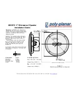
MA-3013
Brand: poly-planar Pages: 1

Ology Walkstation 1451458001
Brand: Steelcase Pages: 38

MHL 108 WASH 150.509
Brand: Beamz Pages: 32


