Standard Horizon CP150, Owner'S Manual
The Motorola CP150 is a versatile two-way radio that ensures clear and reliable communication in any environment. Accompanied by a comprehensive user manual, users can easily navigate its features and functions, empowering them to optimize its performance. Download the free user manual from manualshive.com to unlock the full potential of your CP150.
Share
Download


Reviews:
No comments
Related manuals for CP150
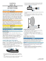
GXM 54
Brand: Garmin Pages: 4

EFT60
Brand: LabShack Pages: 2

AO2500-3-PTM
Brand: Trango Systems Pages: 2

PAL-4010OCF
Brand: Palomar Pages: 2

LBE-M5-OMNI
Brand: Ubiquiti Pages: 24

10008380
Brand: AR Pages: 30

RLA4G
Brand: K&M Burkhard Reuter Pages: 7

Wideband High Gain Digital Aerial
Brand: Labgear Pages: 2

KV2
Brand: Diamond Antenna Pages: 3

CPVU8
Brand: Diamond Antenna Pages: 4

15-4CD Skywalker
Brand: CUSHCRAFT Pages: 6

CMAX-DMF4-43-Wi53
Brand: CommScope Pages: 5

Versa2une SLV
Brand: Shively Labs Pages: 50

EG-IoT--4AB1
Brand: Ercogener Pages: 35

SC52
Brand: RSE Pages: 12

400CP30A
Brand: M2 Antenna Systems Pages: 8

1623
Brand: MFJ Pages: 9

HF-PRO-2-PLUS-T
Brand: Komunica Pages: 2


