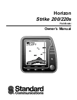
background image

Horizon

Strike 200/220s

Fishfinder

Owner’s Manual

Summary of Contents for Horizon STRIKE 200

Page 1: ...Horizon Strike 200 220s Fishfinder Owner s Manual ...

Page 2: ...efective or not up to factory specifications SCC will pay all labor charges incurred in providing such warranty service To obtain warranty service the defective product must be returned to SCC together with proof of the date of purchase The Purchaser must pay any transportation expenses in returning the product to SCC SCC will examine the product and respond to the Purchaser in approximately four ...

Page 3: ...Display and Operating Modes 9 Echo mode 9 Autofish mode 9 Analogue scope function 10 Navigate Mode 10 Changing the mode of operation 11 Range function 11 Setting the display range 11 Gain function 12 Setting the gain 12 Display scroll speed 13 Setting the scroll speed 13 Alarms 14 Anchor Drag Alarm 14 Setting the alarms 14 Setup Menu 15 Changing the setup functions 15 Setup Menu Speed Temperature ...

Page 4: ... and 220s The more you know and understand about the capabilities of the unit the better it will perform for you Display Size 4 100mm Diagonal 3 x 3 82 mm x 76 mm Display Type STN temperature compensated Display Matrix 100 x 64 pixels Input Voltage 10 to 18 volts DC 150 mA max lights on Backlighting Even illumination Seven levels plus off Operation Temperature 32 F to 104 F ambient 0 C to 40 C Mov...

Page 5: ...ation of the display head and bracket When installing the display head select a position 3 2 81 5 1 4 35 0 5 2 132 0 5 25 133 0 5 9 149 0 power page Horizon Strike 200 Strike 200 lamp alarm where it will be at least 12 300 mm away from the compass at least 12 300 mm away from any radio transmitter such as the VHF easy to read by the helmsman and crew while under way protected from physical damage ...

Page 6: ...er projections from the hull that may cause aerated water to flow over the face of the transducer be away from the propeller be at least 150 mm 6 away from the keel of the boat Poor Location Poor Angle Good Location and Angle Good Location 6 Mounting Once the best location of the transducer is determined hold the transducer and bracket against the transom The bottom surface of the transducer needs...

Page 7: ...onnect the red wire of the two core power cable to the positive supply and the black wire to the electrical ground The shortest and most direct connection to the boat s battery will help to eliminate any problems due to voltage drop or electrical interference Finally drill a hole and insert the third screw in the middle of the bracket It is advisable to fill holes with a sealing compound before in...

Page 8: ...l display only the raw electronic signals Experienced users can use this mode to extract even more information about the water and seabed conditions Note Momentarily pressing the power key removes or displays depth speed and temperature data depth only in the Strike 200 from the upper left corner of the display The format chosen is retained in memory when the power is switched off Menu selection s...

Page 9: ...This mode is very useful for the experienced user The digital display in this sample window is indicating the depth of the bottom The display units are also user selectable Autofish mode The Autofish mode automatically analyses the return echoes and displays echoes with fish icons the bigger the echoes the bigger the icon The return echo is caused when the sonar beam strikes the air stored in the ...

Page 10: ...tion Analogue Scope Current Echo The Analogue scope function is available in either the Echo or Autofish modes This feature displays an intensity graph of the current echoes down the right hand side of the screen The information can be used to help determine the type of bottom structure and the size of fish The strength of the echo is proportional to size or number of pixels visible in the analogu...

Page 11: ... the water down to the lower depth limit you have selected This means that the sea bed may not be shown if the water is deeper than the selected lower depth limit If Bottom is selected then an upper depth limit must also be entered This mode locks the display to show only echoes between the sea bed and the upper depth limit you have selected The top of the water may not be shown if the water is de...

Page 12: ... loss of signal in the water There are two gain modes that can be selected Manual and Auto If Manual is selected then a gain setting from 0 to 15 must also be entered This will be the value of gain that is always used when displaying information on the screen A low gain number may be suitable in shallow water but will need to be increased for deep water operation If Auto is selected then the gain ...

Page 13: ... will work better with higher boat speeds The slower scroll speeds are more suitable for slow speed trolling and slower vessels The most suitable scroll speed is determined by experimentation Setting the scroll speed Press the page key until the speed menu is displayed Press either the key or the key to move the pointer to the desired scroll speed Press the power key to accept the choice and retur...

Page 14: ...isabled with a single key press The alarm indicator bar on the top left of the display shows which alarms have been selected They are fish F shallow S and deep D Fish Alarm Alerts you with a single short signal when an object that could be a fish is detected The alarm for a small fish is shorter than the alarm for a bigger fish Shallow Alarm Alerts you when the water depth is shallower than the sh...

Page 15: ...e used to show depth from the water surface to the bottom When entering a zero as an offset the fishfinder will display depth of water below the transducer Simulation Mode This setting will enable a training mode which allows you to learn to use all the different features in this instrument LCD Contrast You can adjust contrast level from 0 to 7 to match your preference Special circuitry will also ...

Page 16: ... the pointer to the required setup item Use the V or the key to adjust the setting to the desired value Press the power key to accept the choice and return to normal display mode Speed Comparison Method Use the following sequence to adjust the speed displayed to match that of another craft or the speed displayed on a GPS receiver Enter the Speed calibration mode as described on page 16 of the manu...

Page 17: ...e transducer is pointing straight down 2 Electrical noise from the boat s motor can interfere with the Fishfinder This causes the Fishfinder to automatically decrease the gain level unless the gain control has been set manually The Fishfinder thus eliminates weaker signals such as fish or even the sea bed from the display 3 Manual gain may be set too low if you have the instrument set in manual mo...

Page 18: ... Part Numbers Accessory SCC Part DST220 Paddle Wheel Kit 602007011A Mounting Bracket 160006020A Swivel Bracket 106667020A MB Knobs 154003016A Washers 581004030A Mounting Bracket Kit 602008011A contains all of the above brackets knobs and washers ...

Page 19: ...MN000045 1950702B Standard Communications Corp P O Box 92151 Los Angeles CA 90009 2151 Telephone 310 532 5300 STANDARD COMMUNICATIONS CORP ALL RIGHTS RESERVED PRINTED IN NEW ZEALAND MARCH 1998 ...

Page 20: ...sing both the Alarm and Lamp keys simultaneously will switch the alarm off without changing the depth How to Calibrate Speed Log Method Strike 220s only Go to the SETUP 2 Menu RESET LOG and reset the log to zero Travel a known distance of at least a nautical mile between two points in a straight line Best results are achieved in calm conditions where there is minimal current best at high or low ti...

Reviews: