SPX Cooling Technologies MARLEY MH MHF702, User Manual
The SPX Cooling Technologies MARLEY MH MHF702 is a premium cooling tower designed for high performance. Ensure proper installation and maintenance by referring to the comprehensive User Manual. Download it for free from our website and optimize the efficiency and longevity of your cooling system.
Share
Download


Reviews:
No comments
Related manuals for MARLEY MH MHF702
JR-N40B
Brand: Haier Pages: 8
JQ-F110C
Brand: Haier Pages: 8
JQ-F160B
Brand: Haier Pages: 8
JF-ND110A
Brand: Haier Pages: 16
JF-NC429A
Brand: Haier Pages: 8
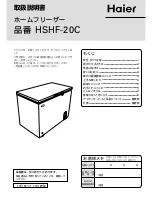
HSHF-20C
Brand: Haier Pages: 8
LW-194B
Brand: Haier Pages: 16

ARCTIS A 40100 GS
Brand: AEG Electrolux Pages: 28

HCE321DK
Brand: Haier Pages: 62

U355B
Brand: STATESMAN Pages: 12

Imperial 216769700
Brand: Imperial Pages: 10

0738
Brand: Taylor Pages: 60
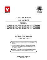
ULF001C
Brand: Yamato Pages: 20

TAYLOR C151
Brand: Frigomat Pages: 64

BD-108E
Brand: Haier Pages: 10

BD-138HMC
Brand: Haier Pages: 16

BD-106G
Brand: Haier Pages: 8

BD-222HEF
Brand: Haier Pages: 20


