background image


ABN 92 510 718 068


Web site: 

http://www.spiritdesign.com.au 


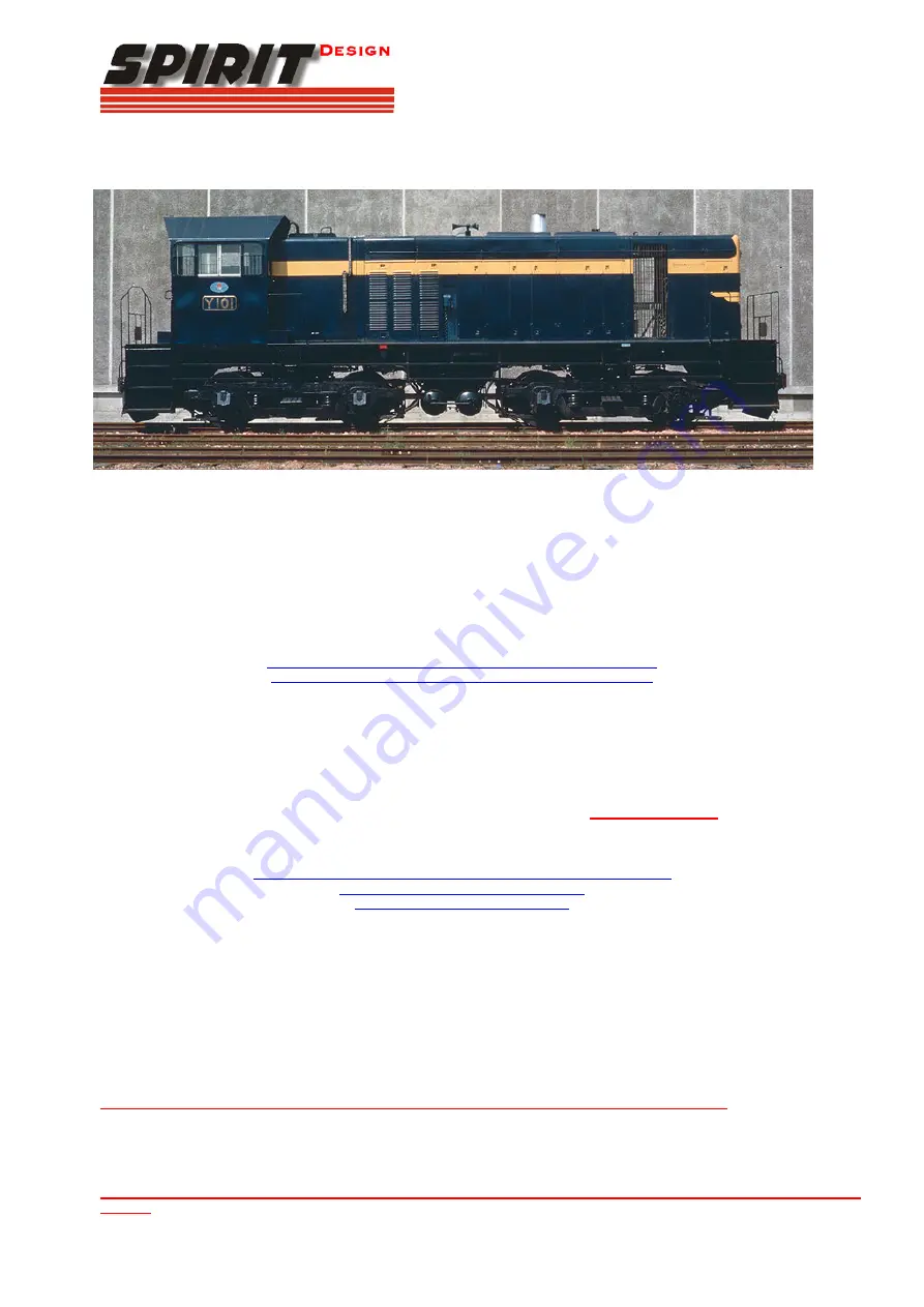
SDLocoY1 - Victorian Railways Y class diesel-electric. 

Requires LifeLike SW9/1200 loco to complete, available separately. 

Thank you for purchasing this kit and I hope you get many hours of enjoyment from it.  Chris Pearce (Spirit Design) 


Brand new Y101 arrives from Clyde and is seen outside Dynon.  Victorian Railways photo 


Basic history: The Y class was the second-largest diesel class of the Victorian Railways with 75 members being built by Clyde’s 
Granville workshops in 3 batches between 1963-1968.  Utilising bogies off scrapped swing door electric trains and featuring a 6-
cylinder EMD 567 and later a 645 engine they were highly regarded by crews and were a versatile go-anywhere engine.  The long 
hood is designated the no1 end and controls were arranged accordingly.  The fleet was seen over the entire VR system with 4 always 
on the standard gauge.  Later on, in life, they received the V/line orange and grey livery and this was later replaced on the 
remaining active units with the new V/line red and blue.  Some were fitted with DOO window openings altering their appearance.  A 
few have made their way into private tourist railways and are still giving reliable service. 
 
Soldering:  
Always clean up soldered joints as you progress, as it’s easier in the long run.  For an understanding of soldering it 
would pay to visit the following sites for information on soldering before attempting your first kit. 

http://themodelmakersresource.co.uk/articles/article012.html


http://www.dccconcepts.com/index_files/DCCsoldering1.htm


Tools needed:
 small files, sanding sticks, fine grade sandpaper, fast-drying wood glue, Selley’s Kwik Grip hydrocarbon-based, 
‘Duck Bill’ (flat – no teeth) and long nose pliers, Plyobond or superglue, soldering iron, solder, flux, Exacto knife, scissor clamps, 
weights, soldering aids, Blu-Tak, 0.3mm drill bit, pin vice, tweezers. 
 
Other items: decoder wire, 2B pencil, paint, couplers, LifeLike SW9/1200 loco for motor, bogies, weights and phosphorous bronze 
pickups etc 
 
Assembly Instructions: Some steps require close attention and they are highlighted 

in bold and italics!

  Parts referred to in the 

text are marked (P1)(P2) etc.   All brass parts and their holding tabs should be trimmed and filed after removing from the etch. 
 
Reference photos: 

http://www.victorianrailways.net/motive%20power/ydie/ydie.html


http://www.robx1.net/index/index.htm


http://www.pjv101.net/index.htm


Train Hobby Y class profile book 

 
Walkway: 

1.


Cut the centre section holding the small parts away from the walkway etch (P1) 

2.


Remove the walkway (P1) from the etch and fold sides up to 90degrees using a ‘Hold ‘n’ Fold’ or between 2 bars of 
hardened ground steel 

3.


Bend ends of the walkway (headstock skirts) to 90 degrees. 

4.


Fold a staircase side (P2), then the bottom of the step up to meet the side and solder.  Do this for all 4 (P2) staircases 

5.


Tests fit a staircase (P2) and once satisfied with the fit, solder it into the floor making sure that the tab in the top slots into 
the hole provided in the walkway.  Also, make sure the staircase is square and straight with the front/rear walkway and the 
headstock skirts.  Then solder the edge of the stair casing to the walkway skirt.  Repeat for the other 3 staircases (P2).  

Note the side part of the case is positioned away from the front/rear skirt of the walkway


6.


Where the stair casing (P2) comes through the walkway (P1), cover this area over with solder and file the tab to make the 
walkway decking flush 

7.


Clean up any excess solder on the completed walkway and make sure the centre area is free from etching holding tabs and 
set aside once the entire walkway is flat and straight when sitting on a flat surface 

8.


Make sure that the walkway is straight and flat and if twisted use pliers/steel bars to achieve a perfectly flat 
surface

.  See the walkway picture below 

Summary of Contents for SDLocoY1

Page 1: ...ssor clamps weights soldering aids Blu Tak 0 3mm drill bit pin vice tweezers Other items decoder wire 2B pencil paint couplers LifeLike SW9 1200 loco for motor bogies weights and phosphorous bronze pickups etc Assembly Instructions Some steps require close attention and they are highlighted in bold and italics Parts referred to in the text are marked P1 P2 etc All brass parts and their holding tab...

Page 2: ...s for the remaining 2 cab handrails into the holes provided If you need to open the holes up use a 0 3mm or no79 80 drill to clear away excess solder 7 Glue a loco headlight P5 into the square above the front door window Cab roof Note The large fold lines are on the underside of the cab roof 1 Insert 2 lift rings P23 into the holes provided on top of the roof P7 and solder glue from underneath Enl...

Page 3: ...ong nose pliers 10 Using your hands fold up the sides of the long hood Don t worry about the section near the cab not matching the profile as yet 11 Bend the rear long hood nose up to meet the sides of the long hood and pay attention so that the bottom edge meets the side s bottom edges as well This may take a few pushes and tweaks with the pliers to achieve this Once satisfied solder one edge bot...

Page 4: ... See photo below 3 Fit a plywood step P15 on the floor of the walkway behind the rear cab door 4 Fit a plywood step P15 on the floor of the walkway in front of the cab front door 5 Glue lift rings P23 into the 3 holes provided on the long end roof and shown below in the diagram 6 Glue the long hood rear wall light P5 onto the square provided 7 In the first hole P14 behind the cab bend a small piec...

Page 5: ...e attached to the body 3 Remove the cab shell after unplugging the centre handrails from the cab The cab weight will be used later 4 Pushing down on the exposed mechanism whilst holding the walkway gradually slide the mechanism out of the plastic shell being careful not to damage the phosphor bronze pickups LifeLike mechanism with the shell removed 5 Remove the long hood from the walkway and dispo...

Page 6: ...the cab end of the motor cut out hole paying very careful attention so that it sits square and vertical with the chassis floor The scribed line points away from the motor and to the headstock end 5 Repeat the same procedure for the wide motor mounting fork P27 that is for the long hood again making sure that the scribed line points away from the motor and to the other headstock end 6 Run beads of ...

Page 7: ...ng to the top Push the motor down into the cradle until snaps into the forks paying attention so that the decoder wires sit in the rear slots provided in the chassis 7 Solder the 18mm decoder wire to the long phosphor bronze tab 8 Solder the 12mm decoder wire to the long phosphor bronze tab 9 Make sure the pickups are at about 30 degrees 10 Glue P36 coupler spacers at each end of the chassis so th...

Page 8: ...urning to get the coupler into position or you can file a very small amount on each side and the bottom of the coupler pocket to allow the unit to slide in from the front Painting The whole etch needs to be cleaned before priming and final colour application All excess solder should be minimised There are several ways of cleaning brass but to bathe the brass in warmed Vinegar for 20 minutes is rec...

Page 9: ...at Seymour 1988 Chris Pearce Y134 Courtesy of Peter Vincent Y 122 Dynon 1980 s Note the fuel gauge compared to Y173 below Chris Pearce Long hood end of Y112 note the missing VR in the chevron Photo courtesy of Mark Bau Air tank arrangement courtesy of Peter ...

Page 10: ...uel tank pipe cab end Photo courtesy Dave Crowhurst Fuel tank top side view Photo courtesy Dave Crowhurst Fireman s side Photo courtesy Dave Crowhurst Driver s side Photo courtesy Dave Crowhurst Y139 doing what it does best Photo courtesy of Geoff Winkler ...

Reviews: