


IM-P192-02
MI Issue 2
1
IM-P192-02
MI Issue 2
1920050/2
1. Safety information
2. General product
information
3. Installation
4. Commissioning
5. Maintenance
6. Spare parts
7. Fault finding
8. Settings table
© Copyright 2016
Printed in GB
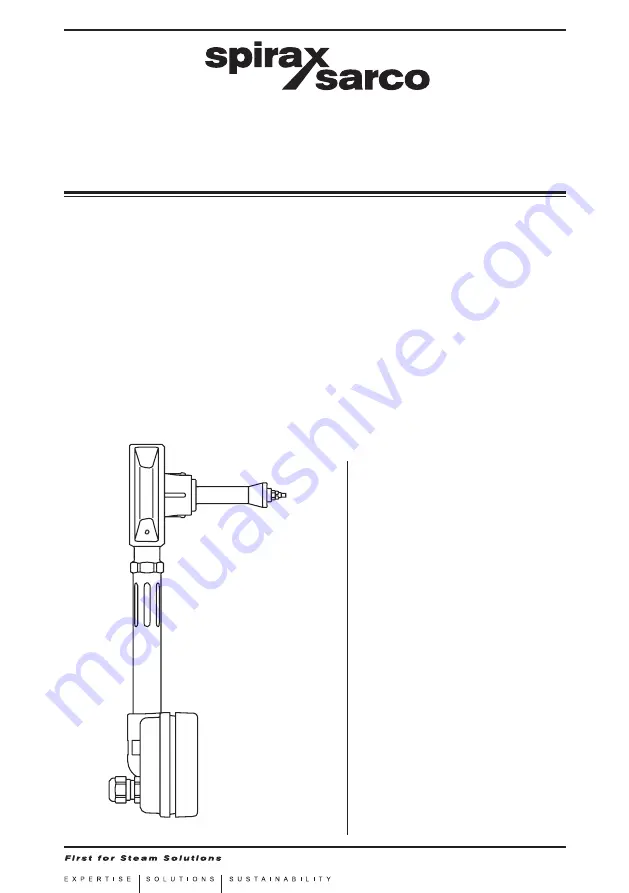
TVA Flowmeter
for Saturated and Superheated Steam Service
Installation and Maintenance Instructions


