1 |
S p e d o 2 2 3 2 I n s t r u c t i o n M a n u a l
S p e d o U K L t d
1
Spedo Optical Loop Interface 2232 Instruction Manual
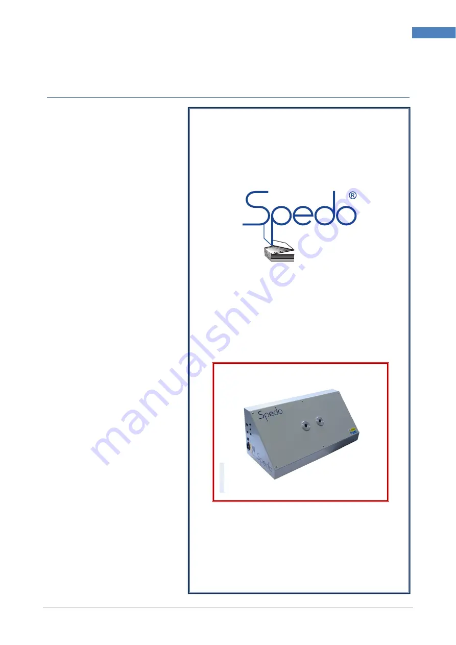
Spedo Optical Loop Interface 2232
Instruction Manual
Issue 2
Spedo UK Limited
76 Woolmer Way
Bordon
Hampshire
GU35 9QF
ENGLAND
Telephone:
+44 (0) 1420 487 447
Fax:
+44 (0) 1420 477 827
Email:
Web:
www.spedouk.com