Speco VLD1A, User Manual
The Speco VLD1A User Manual is an essential resource for maximizing the functionality of this cutting-edge product. Easily downloadable and completely free, this manual provides step-by-step instructions and valuable insights. Visit our website to download it and unlock the full potential of your Speco VLD1A device.
Share
Download


Reviews:
No comments
Related manuals for VLD1A
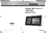
DPF 1000
Brand: Hama Pages: 9

D595 - 5MP Digital Camera
Brand: Olympus Pages: 156

FINEPIX J27
Brand: FujiFilm Pages: 125
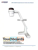
QPC 30M
Brand: Qomo Pages: 10

MX-20, MX-15, RX-20, ad RX-15
Brand: RoboSHOOT Pages: 56

Hi-matic 7
Brand: Minolta Pages: 21

ID-650VDN
Brand: Genesis CCTV Pages: 3

ADMPF119
Brand: Aluratek Pages: 1
AVerVision355af
Brand: Avermedia Pages: 43

ZOOM 105-R
Brand: Pentax Pages: 53

HDVR245H
Brand: Gator Pages: 13

CAMEDIA C-480 ZOOM
Brand: Olympus Pages: 100

DF4820HD-DN
Brand: dallmeier Pages: 36

42990208
Brand: anko Pages: 11

61-844SW
Brand: IDEAL Pages: 23

DXF 01000
Brand: TECH FIVE Pages: 28

21146
Brand: Walimex Pro Pages: 32

Lumix DMC-FZ1
Brand: Panasonic Pages: 108


