South bend TURN-X SB1039, Owner'S Manual
The South bend TURN-X SB1039 Owner's Manual is essential for understanding how to operate this high-quality product. You can easily download the manual for free from manualshive.com, ensuring you have all the necessary information to make the most out of your South bend TURN-X SB1039.
Share
Download


Reviews:
No comments
Related manuals for TURN-X SB1039
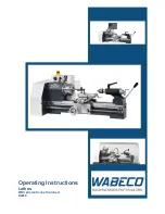
D4000
Brand: WABECO Pages: 78

G0698
Brand: Grizzly Pages: 52

70-3040
Brand: Rikon Power Tools Pages: 32

REVO 15
Brand: laguna Pages: 43

321378
Brand: Jet Pages: 56

95647
Brand: Central Machinery Pages: 8

90692
Brand: Central Machinery Pages: 14

33684
Brand: Central Machinery Pages: 18

98676
Brand: Central Machinery Pages: 19

CENTRAL MACHINERY 65345
Brand: Central Machinery Pages: 22

CENTRAL MACHINERY 44859
Brand: Central Machinery Pages: 31

CENTRAL MACHINERY 45861
Brand: Central Machinery Pages: 41


