South Bend Tools SB1099, Owner'S Manual
The South Bend Tools SB1099 Owner's Manual is a comprehensive guide to effectively use your SB1099 tool. You can easily download this manual for free from our website. Get step-by-step instructions, safety guidelines, and maintenance tips to maximize the performance of your SB1099 tool. Download now from manualshive.com.
Share
Download


Reviews:
No comments
Related manuals for SB1099

BDC-1112
Brand: Blastrac Pages: 16

E-100
Brand: Donaldson Torit Pages: 20

RFWP
Brand: Donaldson Torit Pages: 72

MJ Series
Brand: Amano Pages: 40

Handte Vortex Dual
Brand: Camfil Pages: 30

FlexPAK Standard
Brand: Nederman Pages: 34
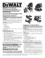
DWE575DC
Brand: DeWalt Pages: 2

4906302924
Brand: Scheppach Pages: 24

KC-3108C
Brand: King Industrial Pages: 11


