Sony WRR-850A, Operating Instructions Manual
The Sony WRR-850A is an advanced wireless receiver offering seamless connectivity for audio professionals. Enhance your recording experience with this high-performance device. Unlock its full potential by downloading the Operating Instructions Manual for free from our website, providing you with all the necessary guidance to optimize its features.
Share
Download


Reviews:
No comments
Related manuals for WRR-850A
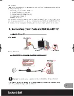
Medi TV
Brand: Packard Bell Pages: 48

AT-200Pro
Brand: LDG Pages: 23

AT-100AMP
Brand: LDG Pages: 12

U65 DUOS
Brand: IconBiT Pages: 17

T-4711
Brand: Onkyo Pages: 20

WJ-ND300A
Brand: Panasonic Pages: 66

HD HomeRun PRIME
Brand: SiliconDust Pages: 6

HDRack
Brand: SiliconDust Pages: 19

LU-SOLO-HDMI
Brand: LiveU Pages: 16

RFDM1R
Brand: Ambery Pages: 6

MN-2000
Brand: DRAKE Pages: 12

RFX8320J
Brand: Rockford Fosgate Pages: 4


