Sony UP55MD, Instructions For Use Manual
The Sony UP55MD is a high-resolution medical-grade printer designed for producing exceptional image quality. For detailed instructions on how to operate and maximize its capabilities, refer to the downloadable user manual and brochure available for free at manualshive.com. Enhance your experience with comprehensive product information and step-by-step guidance.
Share
Download


Reviews:
No comments
Related manuals for UP55MD

PRO
Brand: m3d Pages: 23

PRO
Brand: m3d Pages: 26
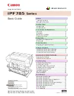
image Prograf iPF785 Series
Brand: Canon Pages: 136

A1
Brand: GBC Pages: 110

M Series
Brand: Xerox Pages: 2

BJC-S530D
Brand: Canon Pages: 96

BJC-S500
Brand: Canon Pages: 2

BJC-S300
Brand: Canon Pages: 2

BJC-80
Brand: Canon Pages: 2

BJC-6000 Series
Brand: Canon Pages: 10

BJC-55 Series
Brand: Canon Pages: 2

BJC-5100 Series
Brand: Canon Pages: 2

BJC-50
Brand: Canon Pages: 4

BJC-4400 Series
Brand: Canon Pages: 15

BJC-3000 Series
Brand: Canon Pages: 8

BJC-3000 Series
Brand: Canon Pages: 2

BJC-2100 Series
Brand: Canon Pages: 9

BJC S600
Brand: Canon Pages: 11


