Summary of Contents for U-Ceiver ICB-U655
Page 4: ... 4 SECTION 2 GENERAL This section is extracted from instruction manual ...
Page 5: ... 5 ...
Page 10: ......
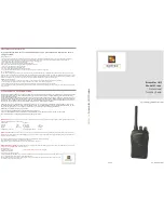
The Sony U-Ceiver ICB-U655 is a versatile and powerful device that offers seamless performance for your everyday needs. For user convenience, detailed Operating Instructions are available for free download on our website, manualshive.com. Enhance your experience and make the most out of your product with the comprehensive manual provided.
Page 4: ... 4 SECTION 2 GENERAL This section is extracted from instruction manual ...
Page 5: ... 5 ...
Page 10: ......