1
SERVICE MANUAL FE-1
CHASSIS
MODEL
COMMANDER DEST CHASSIS NO.
MODEL
COMMANDER DEST CHASSIS NO.
SELF-DIAGNOSTIC FUNCTION
KV-21M5D
RM-883
AEP
SCC-Q04M-A
KV-21T5D
RM-883
AEP
SCC-Q04N-A
KV-21M5K
RM-883
OIRT
SCC-Q03V-A
KV-21T5K
RM-883
OIRT
SCC-Q03X-A
KV-21T5R
RM-883
OIRT
SCC-Q03W-A
®
TRINITRON
®
COLOR TV
M I C R O F I L M
Layer 1
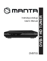
RM-883
PROGR
MENU
N
/