Sony super motion hdc4300, Service Manual
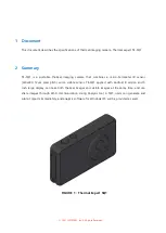
The Sony Super Motion HDC4300 is a state-of-the-art camera system designed for capturing stunning slow-motion footage. Easily operate this advanced device with the help of our comprehensive user manual, available for free download on manualshive.com. Discover the full potential of your Sony HDC4300 with our detailed manual.
Share
Download


Reviews:
No comments
Related manuals for super motion hdc4300

ED 14-42mm f3.5-5.66 EZ
Brand: Olympus Pages: 15

IC-1500 series
Brand: Edimax Pages: 2

S71 MagiCam
Brand: AEE Pages: 82
TE-SQ1
Brand: i3system Pages: 8

B5110
Brand: Zavio Pages: 13

Clip CH50 Series
Brand: InfiRay Pages: 25

EHN3261
Brand: EverFocus Pages: 16

HM-TD2037T-10/X
Brand: Hikmicro Pages: 141

DK-H100
Brand: Hitachi Pages: 2

DK-Z50
Brand: Hitachi Pages: 2
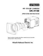
DK-H100
Brand: Hitachi Pages: 48

Z-HD5000
Brand: Hitachi Pages: 8

DK-Z50
Brand: Hitachi Pages: 48

DWC-C273W
Brand: Digital Watchdog Pages: 28

Schneider D-XENOGON 35
Brand: Samsung Pages: 1

SCL-T3755
Brand: Samsung Pages: 2

Samsung 18-55mm
Brand: Samsung Pages: 2

EX-M60SB
Brand: Samsung Pages: 2


