


Australian Model
New Zealand Model
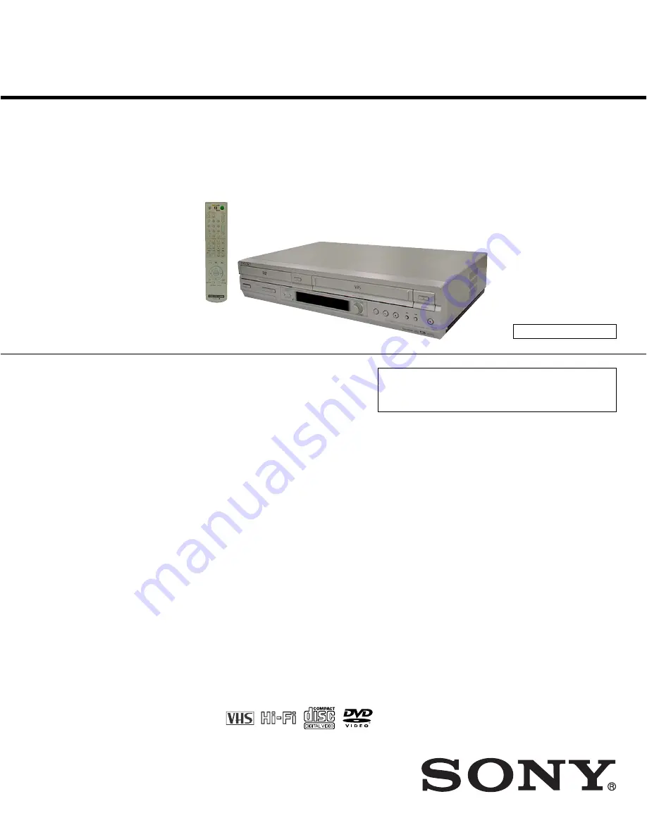
SLV-D940P AZ
Middle East Model
SLV-D940P EA/D940P ME
SERVICE MANUAL
DVD PLAYER/
VIDEO CASSETTE RECORDER
SPECIFICATIONS
RMT-V503D
TS-10 MECHANISM
Refer to the SERVICE MANUAL of VHS MECHANI-
CAL ADJUSTMENT MANUAL VII for MECHANICAL
ADJUSTMENTS. (9-921-790-11)
PAL NTSC
— Continued on next page —
RMT-V503D
SLV-D940P AZ
SLV-D940P AZ/D940P EA/D940P ME
System
Laser
Semiconductor laser
Signal format system
PAL/(NTSC), MESECAM
Channel coverage
SLV-D940P AZ
B/G:VHF E2 to E12/UHF E21 to E69/
CATV S01 to S05, S1 to S41
B/B: VHF R1 to R12/UHF R21 to R69
SLV-D940P ME/EA
B/G:VHF E2 to E12/UHF E21 to E69/
CATV S01 to S05, S1 to S41
D/K: VHF R1 to R12/UHF R21 to R69
I: VHF SA4 to SA13/UHF B21 to B69/
CATV S01 to S05, S1 to S41
RF output signal
UHF channels 21 to 69 (B/G, D/K, I)
UHF channels 28 to 69 (B/B)
Aerial out
75-ohm asymmetrical aerial socket
Tape speed
SP:
PAL
23.39 mm/s (recording/playback)
NTSC 33.35 mm/s (recording*(line input
only)/playback)
LP: PAL
11.70 mm/s (recording/playback)
NTSC 16.67 mm/s (playback only)
EP: NTSC 11.12 mm/s (recording*(line input
only)/playback)
* SLV-D940P ME/EA only
Maximum recording/playback time
10 hrs. in LP mode (with E300 tape)
Rewind time
Approx. 1 min. (with E180 tape)
Inputs and outputs
LINE IN 1/LINE-2 IN
VIDEO IN, phono jack (1)
Input signal: 1 Vp-p, 75 ohms, unbalanced, sync
negative
AUDIO IN, phono jacks (2)
Input level: 327 mVrms
Input impedance: more than 47 kilohms
LINE OUT
VIDEO OUT, phono jack (1)
Output signal: 1 Vp-p, 75 ohms, unbalanced,
sync negative
AUDIO OUT, phono jacks (2)
Standard output: 327 mVrms
Load impedance: 47 kilohms
Output impedance: less than 10 kilohms
Additional AUDIO OUT, phono jacks (2)
Standard output: 327 mVrms
Load impedance: 47 kilohms
Output impedance: less than 10 kilohoms
DIGITAL OUT (OPTICAL)
Optical output jack/
−
18 dBm
(wave length 660 nm)
DIGITAL OUT (COAXIAL)
Phono jack/0.5 Vp-p/75 ohms
Summary of Contents for SLV-D940P AZ
Page 67: ...3 Block Diagram 3 2 3 1 SLV D940P AZ D940P EA D940P ME ...
Page 68: ...MEMO 3 4E ...
Page 70: ...4 3 4 4 4 1 VCR Main COMPONENT SIDE ...
Page 71: ...4 6 4 5 CONDUCTOR SIDE ...
Page 72: ...4 7 4 8 4 2 DVD Main COMPONENT SIDE ...
Page 73: ...4 10 4 9 CONDUCTOR SIDE ...
Page 74: ...4 12E 4 11 4 4 FUNCTION 4 3 Dial ...
Page 76: ...5 4 5 3 5 1 S M P S ...
Page 77: ...5 6 5 5 5 2 Power Drive ...
Page 78: ...5 8 5 7 5 3 OSD VPS PDS ...
Page 79: ...5 10 5 9 5 4 A2 NICAM ...
Page 80: ...5 12 5 11 5 5 A V ...
Page 81: ...5 14 5 13 5 6 Hi Fi ...
Page 82: ...5 16 5 15 5 7 TM ...
Page 83: ...5 18 5 17 5 8 I O ...
Page 84: ...5 20 5 19 5 9 SYSCON ...
Page 85: ...5 22 5 21 5 10 Logic Function ...
Page 86: ...5 24 5 23 5 11 DVD A V ...
Page 87: ...5 26 5 25 5 12 DVD decoder Servo ...
Page 88: ...MEMO 5 28E ...
Page 116: ...7 18E MEMO ...


